


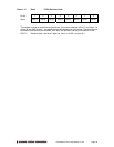

Prometheus CPU User Manual V1.44 Page 48
14. PERFORMING AN A/D CONVERSION
This chapter describes the steps involved in performing an A/D conversion on a selected input
channel using direct programming (not with the driver software).
There are seven steps involved in performing an A/D conversion:
1. Select the input channel
2. Select the input range
3. Wait for analog input circuit to settle
4. Initiate an A/D conversion
5. Wait for the conversion to finish
6. Read the data from the board
7. Convert the numerical data to a meaningful value
14.1 Select the input channel
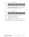
To select the input channel to read, write a low-channel/high-channel pair to the channel register
at base + 2 (see page 35). The low 4 bits select the low channel, and the high 4 bits select the
high channel. When you write any value to this register, the current A/D channel is set to the low
channel.
For example:
To set the board to channel 4 only, write 0x44 to Base + 2.
To set the board to read channels 0 through 15, write 0xF0 to Base + 2.
⇒ Note: When you perform an A/D conversion, the current channel is automatically incremented
to the next channel in the selected range. Therefore, to perform A/D conversions on a group of
consecutively-numbered channels, you do not need to write the input channel prior to each
conversion. For example, to read from channels 0 - 2, write Hex 20 to base + 2. The first
conversion is on channel 0, the second will be on channel 1, and the third will be on channel 2.
Then the channel counter wraps around to the beginning again, so the fourth conversion will be
on channel 0 again and so on.
If you are sampling the same channel repeatedly, then you set both high and low to the same
value as in the first example above. Then on subsequent conversions you do not need to set the
channel again.
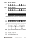
14.2 Select the input range
Select the input range from among the available ranges shown on page 47. If the range is the
same as for the previous A/D conversion then it does not need to be set again. Write this value to
the input range register at Base + 3 (see page 36).
For example:
For ±5V range (gain of 2), write 0x01 to Base + 3.
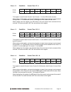
14.3 Wait for analog input circuit to settle
After writing to either the channel register (Base + 2) or the input range register (Base + 3), you
must allow time for the analog input circuit to settle before starting an A/D conversion. The board
has a built-in 10µS timer to assist with the wait period. Monitor the WAIT bit at Base + 3 bit 5.
When it is 1 the circuit is actively settling on the input signal. When it is 0 the board is ready to
perform A/D conversions.