


Prometheus CPU User Manual V1.44 Page 68
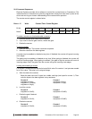
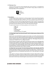
23.7 Watchdog Timer
J9 may be used to connect an external watchdog timer circuit to the CPU. For watchdog timer
programming information, see page 20 and the ZFx86 Training Manual included in the
Documents folder of the Prometheus CD.
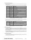
1 Ground
2 Watchdog In
3 Watchdog Out
J9 Pinout
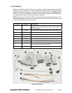
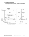
23.8 Installation
The panel board includes a hardware kit containing spacers of various sizes along with screws
and nuts. There are three sizes of spacers: 7mm (0.276”), 14mm (0.551”), and 0.600”. All
hardware for assembling the stack and mounting it to the enclosure front panel is #4-40 thread.
The Pandora enclosure includes an additional hardware kit of #6-32 screws for assembling the
front and back panels to the enclosure body. Refer to the assembly drawings provided with the
panel board for proper assembly of the PC/104 stack and Pandora enclosure.
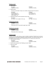
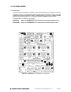
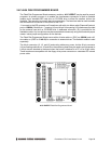
The panel board connects to the following headers on the Prometheus CPU:
J3 Main I/O
J4 Ethernet
J5 USB
J6 Watchdog timer
J11 Input power
J14 Data acquisition (-EA models)
To install the panel board onto the Prometheus CPU board, first remove any jumpers on J6 of the
CPU (upper right corner) since these will interfere with the mating header on the bottom of the
panel board.
Insert the four 7mm male/female hex spacers into the holes on top of the panel board and fix
them in place with the four 14mm female/female hex spacers below. Then plug the panel board
onto the connectors of the CPU board, being careful to align all the connectors properly. Note that
there are mating connectors on all 4 edges of the board for the –EA (analog I/O) version, and
connectors on 3 sides for the -E (no analog I/O) version.
When the boards are properly mated, the 80-pin high-density connectors on the right edges of the
boards will seat completely, while the pin headers on the other sides will show a slight gap. This
is normal and does not cause any problem with reliable connections on these connectors. If you
do not install the 14mm spacers between the two boards, you will still be able to mate the two
boards satisfactorily, but they will be slightly tilted, since the high-density connector has a slightly
larger board-to-board distance than the other pin headers.
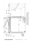
The board stack may be mounted inside the Pandora enclosure in one of two ways. The stack
may “hang” from the front panel, or it may be mounted to both the front and rear panel. The
assembly drawings included with the Pandora enclosure show both options. The stack mounts to
the front panel with four #4 flat head screws that install onto the four spacers on the top of the
panel board as well as 14 #4 screwlocks that connect to the 7 Dsub connectors on the panel
board.
Finally select one of the two options for fixing the bottom of the stack. Either install four #4 pan
head screws on the bottom of the CPU board into the four spacers between it and the panel
board, or attach the four 0.6” male/female round PC/104 spacers on the bottom of the board and
then install four #4 flat head screws through the case’s rear panel into the PC/104 spacers.