


10 Configuring and Monitoring the Switch DNswitch 800
System Information
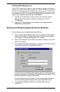
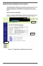
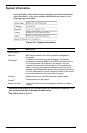
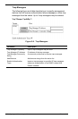
Use the System Information screen to display descriptive information
about the switch, or for quick system identification as shown in the
following figure and table.
Figure 3-2. System Information
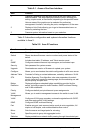
Parameter Description
System Name
1
Name assigned to the switch system.
Object ID MIB II object identifier for switch’s network management
subsystem.
IP Address
2
IP address of the switch you are managing. The switch’s
management supports SNMP over UDP/IP transport protocol.
In this environment, all systems on the Internet, such as
network interconnection devices and any PC accessing the
switch (or running management software) must have an IP
address. Valid IP addresses consist of four decimal numbers, of
0 to 255, separated by periods. Anything outside of this format
will not be accepted by the configuration program.
Location
1
Specifies the area or location where the system resides.
Contact
1
Contact person for the system.
System Up Time Length of time the current management software has been
running.
1
Maximum string length is 255, but the screen only displays 45 characters. You
can use the arrow keys to browse the whole string.
2
The default value is 10.1.0.1