


12 Configuring and Monitoring the Switch DNswitch 800
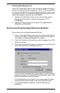
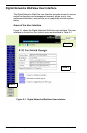
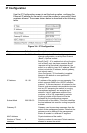
IP Configuration
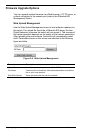
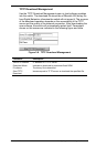
Use the IP Configuration screen to set the bootup option, configure the
Ethernet IP address for the switch, or set the number or concurrent Telnet
sessions allowed. The screen shown below is described in the following
table.
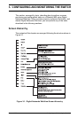
Figure 3-4. IP Configuration
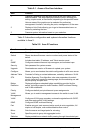
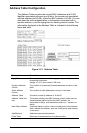
Parameter Default Description
IP State BootP-Get-IP Specifies whether IP functionality is enabled via
manual configuration, or set by Boot Protocol
(BootP). Options include:
BootP Get IP - IP is enabled but will not function
until a BootP reply has been received. BootP
requests will be periodically broadcast by the
switch in an effort to learn its IP address. (BootP
values include the IP address, default gateway,
and subnet mask.)
User-Configured - IP functionality is enabled
based on the default or user specified IP
Configuration.
IP Address 10.1.0.1 IP address of the switch you are managing. The
switch supports SNMP over UDP/IP transport
protocol. In this environment, all systems on the
Internet, such as network interconnection devices
and any PC accessing the switch (or running
management software) are assigned an IP
address. Valid IP addresses consist of four
numbers, of 0 to 255, separated by periods.
Anything outside of this format will not be
accepted by the configuration program.
Subnet Mask 255.255.0.0 Subnet mask of the switch. This mask identifies
the host address bits used for routing to specific
subnets.
Gateway IP Gateway used to pass trap messages from the
switch to the management station. Note that the
gateway must be defined if the management
station is located in a different IP segment.
MAC Address Physical address of the switch.
Number of Telnet
sessions
4 Sets the number of concurrent Telnet sessions
allowed to access the switch.