


5 Configuration D-Link Web Smart Switch User Manual
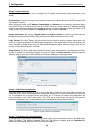
Configuration > 802.1Q VLAN (Asymmetric VLAN)
This function is located in the 802.1Q Configuration page. It allows devices in different VLANs to
communicate with the servers, firewalls or other shared resources in the shared VLAN. This configuration is
accomplished in three steps:
Enabling Asymmetric VLAN function
Creating shared VLAN and access VLAN
Configuring the PVID of access VLAN
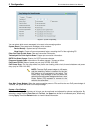
Asymmetric VLAN is especially effective when used in a small network where a L3 routing device is absent,
or if the resource to be shared is not capable of supporting tagged VLAN (for example, a printer).
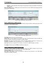
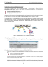
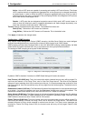
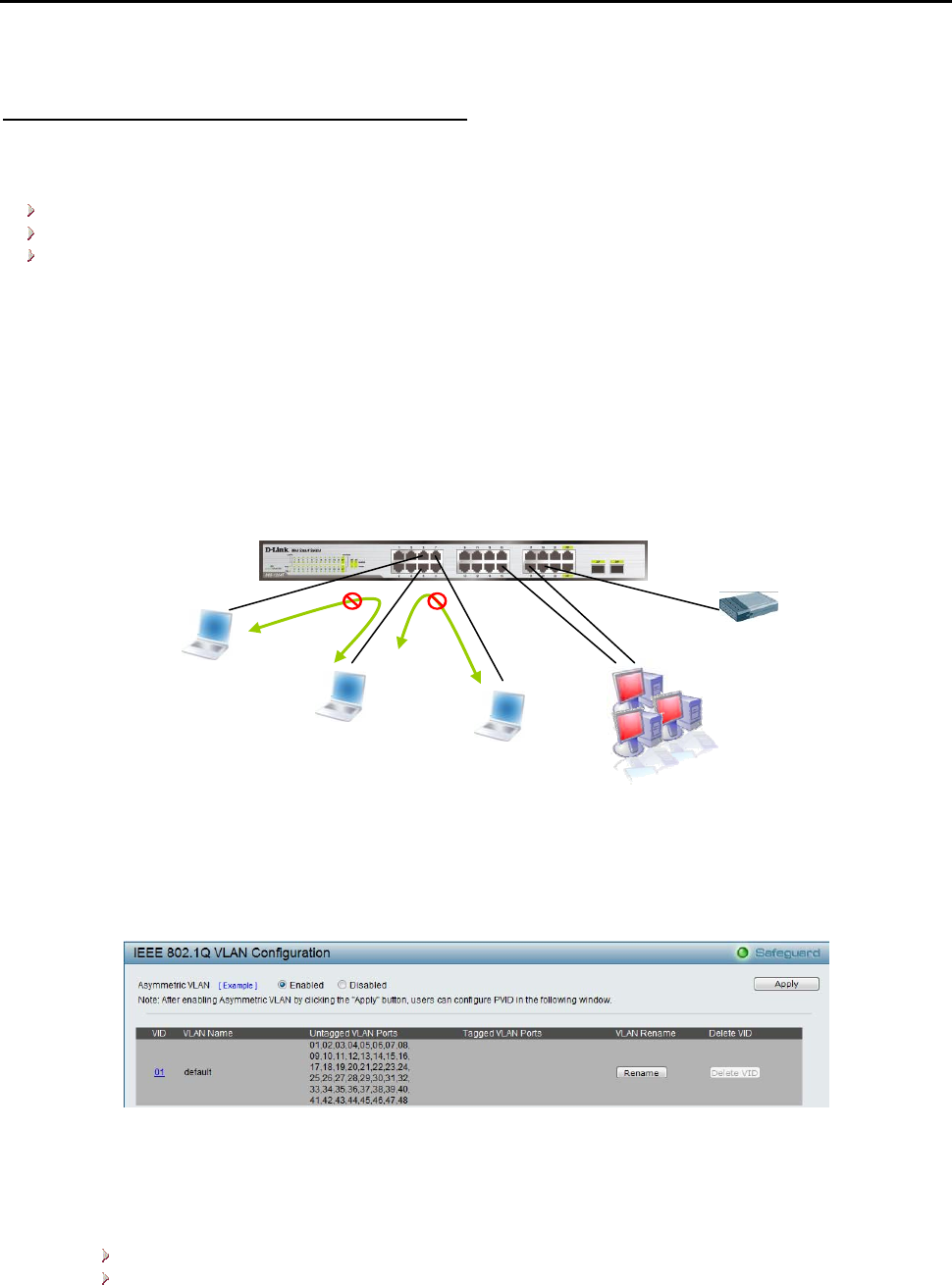
The example below is a typical application of Asymmetric VLAN. Servers and firewall are located in shared
VLAN (default VLAN), and PCs 1, 2 and 3 are located in different VLAN. Because VLANs remain separate,
PCs 1, 2, and 3 cannot communicate with each other; but all of them need to access the servers or the
Internet behind the firewall.
PC 1 (Port 5, V2)
Firewall, V1~V4
Servers, V1~V4
PC 2 (Port 6, V3)
PC 3 (Port 7, V4)
Figure 63 – Configuration > 802.1Q VLAN > Asymmetric VLAN Example
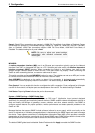
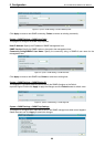
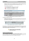
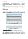
1. Enable Asymmetric VLAN
Enable Asymmetric VLAN and click Apply button. The overlapping VLAN cannot be configured
unless this function is enabled..
Figure 64 – Configuration > 802.1Q VLAN > Asymmetric VLAN - Enabling Asymmetric VLAN
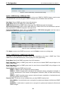
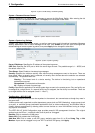
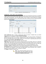
2. Configure the shared VLAN (VLAN 1) and access VLANs (VLAN 2, 3, 4)
In this case, the default VLAN is used as shared VLAN, and the ports that are shared in the network
are:
Ports 15-18 are connected to the server
Port 20 is connected to the firewall
The group of shared ports needs to be included for all the VLANs. Ports 15-18, 20 already belong to
VLAN 1, therefore no changes are needed.
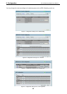
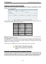
VLAN 2 is configured to include ports 15-18, 20 (shared VLAN ports) and the set of ports to be
separated from the other VLANs (for example, port 5). VLAN 3 and 4 are then configured to include
36