


Data Power Solutions Quick Start Guide
24
Copyright © 2006-2009 Eaton Corporation. All Rights Reserved.
10640205 February 2009
Installing the Battery Temperature Sensor (if batteries are fitted)
This section applies to APS3-059, APS3-061 and APS6-059 dc power systems only.
Each APS3-059, APS3-061 and APS6-059 dc power system is supplied with a battery
temperature sensor and standard 2m (6.5 feet) long cable (factory-fitted to the sensor). Longer
cables are available from your local Eaton dc product representative or you can make up
your own. We strongly recommend limiting the maximum cable length of the battery
temperature sensor to 20m (65 feet) because of noise considerations.
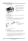
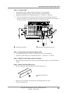
Connecting the Battery Temperature Sensor Cable
There are two screw-clamp terminal blocks at the rear of APS3-059, APS3-061 and APS6 059
dc power systems for terminating the battery temperature sensor cable, the two terminal
blocks are labeled TEMP SENSOR (+) and TEMP SENSOR (-).
• Terminate the Black / White wire at TEMP SENSOR (+) and the Black wire at TEMP
SENSOR (-).
• To ensure reliable connections at the battery temperature sensor terminal blocks, torque
the clamp screws 0.4 – 0.6Nm (3.5 – 5.3 lb-in).
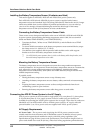
• Use cable-ties (not supplied) and the provided cable-tie holes on the cable support
bracket to tie down the battery temperature sensor cable.
On APS3-061 dc power systems, there is a hole on the battery cable clamp bracket, to tie
down the battery temperature sensor cable.
Mounting the Battery Temperature Sensor
The battery temperature sensor is designed to measure the average ambient temperature
around the batteries. It is important to mount the battery temperature sensor at a location that
truly reflects the average ambient temperature of the batteries. Attaching the battery
temperature sensor to the battery stand (above the middle batteries) may provide the most
reliable temperature reading.
If possible, avoid:
• Placing the battery temperature sensor on top of battery cases.
• Attaching the battery temperature sensor to battery cables, terminals or interconnecting
bars.
• Exposing the battery temperature sensor to direct sunlight and drafts from the air-
conditioning system or open windows.
• Running the battery temperature sensor cable along power or earth cables.
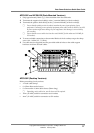
Connecting the APS DC Power System to the AC Supply
APS dc power systems can be connected to single-phase (L-N), two-phase (L-L), three-phase
(L-N) and three-phase (L-L) ac supply systems. Fused ac sockets (one per rectifier) are
available for connecting the APS dc power system to the ac supply. These fused ac sockets are
labeled K1 to K3 on APS3 and K1 to K6 on APS6 dc power systems. AC supply socket K1
powers Rectifier 1, etc. No ac power cords are supplied with APS dc power systems.
AC Supply Requirements
AC Power Cords – The ac power cords (supplying the APS dc power system) must be
suitably rated for the environment and ac distribution system. In addition, these ac power
cords must be approved and installed to comply with local wiring regulations. (See
Specifications on page 28 for ac power cord specifications.) The maximum length of each ac
power cord should not exceed 3m (10 feet), unless local wiring regulations permit otherwise.