


-26-
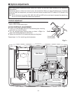
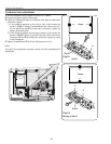
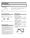
After replacing the Power Board, PF.C. Board, readjust
the Output voltage adjustment as follows.
1. Connect a digital voltmeter to pins 1 (+) and 3 (-) of
K6D.
2. Adjust the voltage by using VR611 as following.
A
C Input Reading
230V 370V ±2V
or 120V 340V ±2V
Caution:
Be sure to connect the lamp when taking this adjust-
ment.
● Circuit Adjustments
CAUTION: The each circuit has been made by the fine adjustment at factory. Do not attempt to adjust the follow-
ing adjustments except requiring the readjustments in servicing otherwise it may cause loss of per-
formance and product safety.
[Adjustment Condition]
● Input signal
Video signal .......................... 1.0Vp-p/75Ω terminated, 16 steps gray scale (Composite video signal)
Computer signal...................... 0.7Vp-p/75Ω terminated, 16 steps gray scale pattern (XGA)
● Picture control mode ...................... “STANDARD” mode unless otherwise noted.
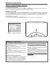
Note:
* Please refer to “Service Adjustment Menu Operation” for entering to the service mode and adjusting the service
data.
Electrical Adjustments
Output Voltage adjustment
1. Receive the 16-step grey scale video signal.
2. Set to VIDEO mode.
3. Enter the service mode.
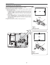
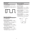
[R-PEDESTAL ADJUSTMENT]
4. Connect an oscilloscope to test point “TP201R”(+)
and chassis ground (-).
5. Select group no. “3”, item no. “14” and change data
value to adjust the pedestal level and black level to be
the same level.
[G-PEDESTAL ADJUSTMENT]
6. Connect an oscilloscope to test point “TP201G”(+)
and chassis ground (-).
7. Select group no. “3”, item no. “15” and change data
value to adjust the pedestal level and black level to be
the same level.
[B-PEDESTAL ADJUSTMENT]
8. Connect an oscilloscope to test point “
TP201B”(+)
and chassis ground (-).
9. Select group no. “3”, item no. “16” and change data
value to adjust the pedestal level and black level to be
the same level.
Pedestal level = Black level
(a)
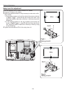
Pedestal adjustment
1. Enter the service mode and select group no. “11” and
item no. “0”. Set data value to “1”.
2. Connect a digital voltmeter to test point “TP12V1” (+)
and chassis ground (-). Select item no.“1” and change
data value to adjust voltage to be 8.0 ±0.1V.
3. Connect a digital voltmeter to test point “TP12V2” (+)
and chassis ground (-). Select item no. “2” and
change data value to adjust voltage to be 9.0 ±0.1V.
4. Select group no. “11” and item no. “0” and set data
value to “3”.
5. Connect a digital voltmeter to test point “TP12V1” (+)
and chassis ground (-). Select item no.“3” and change
data value to adjust voltage to be 13.0 ±0.1V.
6. Connect a digital voltmeter to test point “TP12V2” (+)
and chassis ground (-). Select item no.“4” and change
data value to adjust voltage to be 13.5 ±0.1V.
Fan Voltage adjustment