


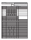
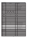
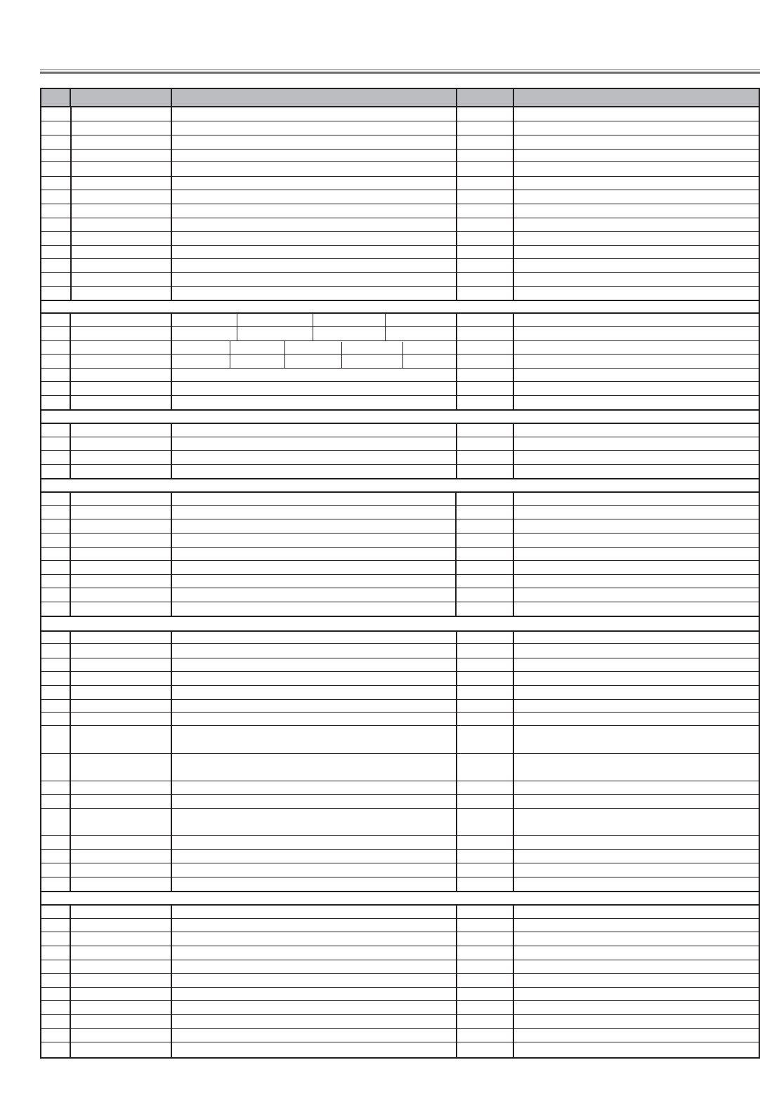
3 REF_R 148 0 ~ 255 ✻ Red white-black level adjustment
4 REF_G 148 0 ~ 255 ✻ Green white-black level adjustment
5 REF_B 148 0 ~ 255 ✻ Blue white-black level adjustment
6 NRS_B 128 0 ~ 255
7 NRS_A 135 0 ~ 255 ✻ NRS adjustment
8 G_V_COM 140 0 ~ 255 ✻ Green common center adjustment
9 B_V_COM 140 0 ~ 255 ✻ Blue common center adjustment
10 R_V_COM 140 0 ~ 255 ✻ Red common center adjustment
11 R_CLMP 63 0 ~ 255 ✻ Red PC offset adjustment
12 G_CLMP 63 0 ~ 255 ✻ Green PC offset adjustment
13 B_CLMP 63 0 ~ 255 ✻ blue PC offset adjustment
14 R_BLK_DC 76 0 ~ 255 ✻ Red pedestal adjustment
15 G_BLK_DC 76 0 ~ 255 ✻ Green pedestal adjustment
16 B_BLK_DC 76 0 ~ 255 ✻ blue pedestal adjustment
Group:4 TA1318
15kHz 31kHz 33kHz 45kHz
0 SEP_LEV 0 0 0 0 0 ~ 3
1080i 720p 480p 575i,PAL,SECAM 480i,NTSC
1 HD_PHASE 36 38 36 32 32 0 ~ 63
2 V_FREQ - - Read only
3H_FREQ - -
4 HD_IN - -
Group:5 LP05 (Turbo)
0 LP05_R_GAIN 128 0 ~ 255
1 LP05_G_GAIN 128 0 ~ 255
2 LP05_B_GAIN 128 0 ~ 255
3 TURBO_GAIN 19 0 ~ 255
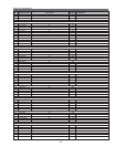
Group:10 Option
0 Lamp Time Monitor - - Read only
1 RS232C Baudrate 0 0 ~ 1 0:19200bps 1: 9600bps
2 Shootout Mode 0 0 ~ 2
1:Mode-1(Change when no signal input) 2:Mode-2(Priority of AV) 0:Disable
3 Cooling Time 3 0 ~ 15 Set cooling time period 1:30 sec.3:90 sec.15:450 sec.0:On conti.
4High-Land SW 0 0 ~ 1 0:Normal mode(Normal operation) 1:Highland mode(max speed in normal)
5V-Sync SW 0 0 ~ 1 0:Vertical-synchronized 1:No vertical-synchronized
6 Color Shading SW 1 0 ~ 1 Color correction 0:No 1:Yes, adjustable but does no store the value
7MCI Output Auto 1 0 ~ 1 Auto: 1, Fixed: 0
6Keystone Option 0 0 ~ 1 Fixed limitation :0, Change limitation to the input: 1
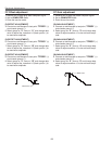
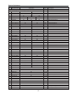
Group:11 Fan Control ✻ Fan voltage adjustment
0Fan Speed Mode 0 0 ~ 3 0:Fan control 1:Min., 2:Mid., 3: Max.it can not be memorized.
1Fan-1 Min Data 44 0 ~ 127 Minimum output data when controlling Fans ✻
2Fan-2 Min Data 63 0 ~ 127 Minimum output data when controlling Fans ✻
3Fan-1 Max Data 217 128 ~ 255 Maximum output data when controlling Fans ✻
4Fan-2 Max Data 236 128 ~ 255 Maximum output data when controlling Fans ✻
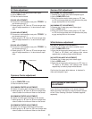
5Temp Low 37 10 ~ 80 Decides output data of DAC for temperature
6Temp High 45 30 ~ 80 Decides output data of DAC for temperature
7Fan-1 Temp Error 61 30 ~ 80 Temperature which CPU judges the abnormal temperature
(optical unit temperature, on Main board)
8Fan-2 Temp Error 51 30 ~ 80 Temperature which CPU judges the abnormal temperature
(outside temperature, on Temp board)
9Fan-1 Speed Monitor - 0 ~ 255 Read only, displays DAC output data
10 Fan-2 Speed Monitor - 0 ~ 255 Read only, displays DAC output data
11 Temp Monitor - 0 ~ 9999 Read only ( Upper 2 byte indicates for Fan-1.
Lower 2 byte indicates Fan-2)
12 Eco mode Fan-1 Min Data 44 0 ~ 127 decides minimum output data at Eco mode.
13 Eco mode Fan-2 Min Data 63 0 ~ 127 decides minimum output data at Eco mode.
14
Eco mode Fan-1 Max Data 217 128 ~ 255 decides maximum output data at Eco mode.
15 Eco mode Fan-2 Max Data 236 128 ~ 255 decides maximum output data at Eco mode.
Group:12 PC Real / AV Cinema
0 PC Real Contrast 32 0 ~ 63
1 PC Real Brightness 32 0 ~ 63
2 PC Real Red 32 0 ~ 63
3 PC Real Green 32 0 ~ 63
4PC Real Blue 32 0 ~ 63
5 PC Real Gamma 8 0 ~ 15
6AV Cinema Contrast 32 0 ~ 63
7AV Cinema Brightness 32 0 ~ 63
8AV Cinema Color 32 0 ~ 63
9AV Cinema Tint 32 0 ~ 63
10 AV Cinema Red 32 0 ~ 63
-32-
Electrical Adjustments
No. Adjustment Item Initial Value Range Description