


-27-
Electrical Adjustments
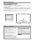
1. Receive the 16-step grey scale computer signal.
2. Set to COMPUTER mode.
3. Enter the service mode.
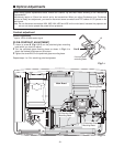
[R-SIGNAL CENTER ADJUSTMENT]
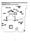
4. Connect a digital voltmeter to test point “TP25R1”(+)
and chassis ground (-).
5. Select group no. “3”, item no. “0” and change data
value to adjust the voltage to be 7.30 ±0.05V.
[G-SIGNAL CENTER ADJUSTMENT]
6. Connect a digital voltmeter to test point “TP25G1”(+)
and chassis ground (-).
7. Select group no. “
3”, item no. “1” and change data
value to adjust the voltage to be 7.30 ±0.05V.
[B-SIGNAL CENTER ADJUSTMENT]
8. Connect a digital voltmeter to test point “TP25B1”(+)
and chassis ground (-).
9. Select group no. “3”, item no. “2” and change data
value to adjust the voltage to be 7.30 ±0.05V.
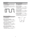
1. Receive the 16-step grey scale computer signal.
2. Set to COMPUTER mode.
3. Connect an oscilloscope to test point “TP3551” (+)
and chassis ground (-).
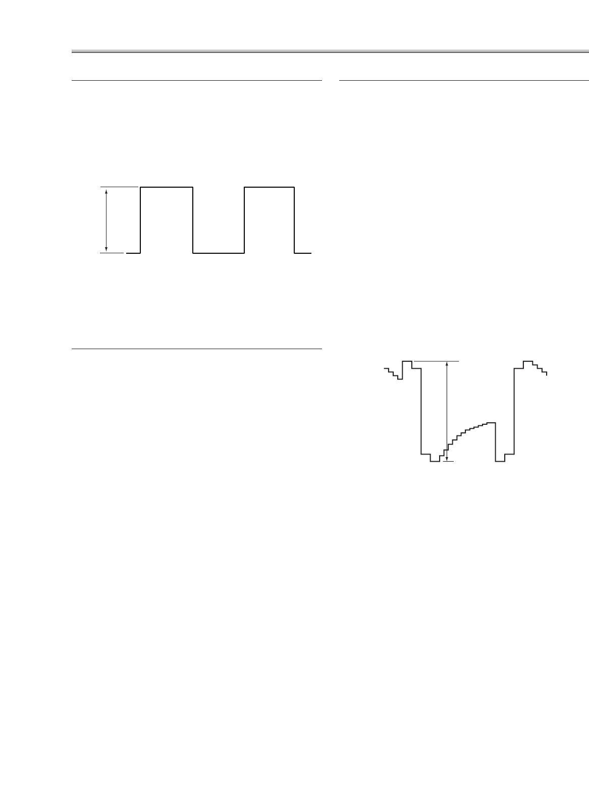
4. Enter the service mode, select group no. “3”, item no.
“7” and change data value to adjust amplitude “a” to
be 4.8 ±0.1V.
(a)
Signal Center adjustment
NRS adjustment
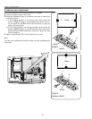
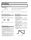
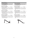
1. Receive the 16-step grey scale computer signal.
2. Set to COMPUTER mode.
3. Enter the service mode.
[R-BLACK ADJUSTMENT]
4. Connect an oscilloscope to test point “TP25R1” (+)
and chassis ground (-).
5. Select group no. “3”, item no. “3” and change data
value to adjust amplitude “a” to be 10.0 ±0.1V.
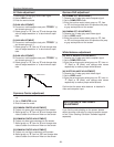
[R-BLACK ADJUSTMENT-]
6. Connect an oscilloscope to test point “TP25G1” (+)
and chassis ground (-).
7. Select group no. “3”, item no. “4” and change data
value to adjust amplitude “a” to be 10.0 ±0.1V.
[R-BLACK ADJUSTMENT-]
8. Connect an oscilloscope to test point “TP25B1” (+)
and chassis ground (-).
9. Select group no. “3”, item no. “5” and change data
value to adjust amplitude “a” to be 10.0 ±0.1V.
(a)
black level
black level
Black Level adjustment