


-28-
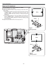
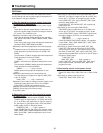
Electrical Adjustments
1. Receive the 16-step gray scale computer signal.
2. Set to COMPUTER mode.
3. Enter the service mode.
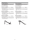
[R-GAIN ADJUSTMENT]
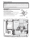
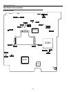
4. Connect an oscilloscope to test point “TP25R1”(+)
and chassis ground (-).
5. Select group no. “2”, item no. “3” and change data
value to adjust waveform “a” to be minimum ampli-
tude.
[G-GAIN ADJUSTMENT]
6. Connect an oscilloscope to test point “TP25G1”(+)
and chassis ground (-).
7. Select group no. “2”, item no. “4” and change data
value to adjust waveform “a” to be minimum ampli-
tude.
[B-GAIN ADJUSTMENT]
8. Connect an oscilloscope to test point “TP25B1”(+)
and chassis ground (-).
9. Select group no. “2”, item no. “5” and change data
value to adjust waveform “a” to be minimum ampli-
tude.
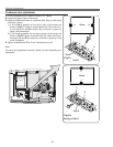
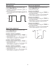
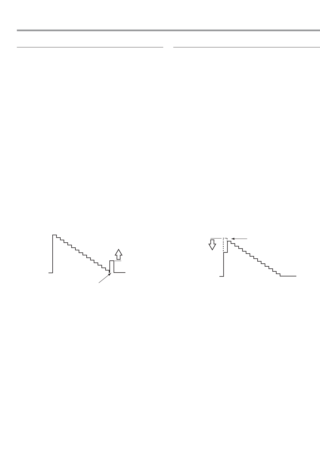
White Level
(a)
PC Gain adjustment
1. Receive the 16-step gray scale computer signal.
2. Set to COMPUTER mode.
3. Enter the service mode.
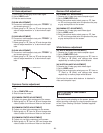
[R-OFFSET ADJUSTMENT]
4. Connect an oscilloscope to test point “TP25R1”(+)
and chassis ground (-).
5. Select group no. “3”, item no. “11” and change data
value to adjust the waveform “a” (black portion ) to
be maximum amplitude.
[G-OFFSET ADJUSTMENT]
6. Connect an oscilloscope to test point “TP25G1”(+)
and chassis ground (-).
7. Select group no. “3”, item no. “12” and change data
value to adjust the waveform “a” (black portion ) to
be maximum amplitude.
[B-OFFSET ADJUSTMENT]
8. Connect an oscilloscope to test point “TP25B1”(+)
and chassis ground (-).
9. Select group no. “3”, item no. “13” and change data
value to adjust the waveform “a” (black portion ) to
be maximum amplitude.
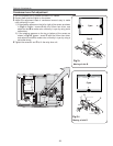
Black Level
(a)
PC Offset adjustment