


-29-
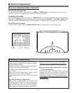
Electrical Adjustments
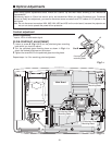
[PC-GAMMA OFF ADJUSTMENT]
1. Receive the 16-step gray scale computer signal.
2. Set to COMPUTER mode.
3. Enter the service mode, select group no. “2”, item
no. “6”and change data value to reproduce the prop-
er gray scale picture on the screen.
[AV-GAMMA OFF ADJUSTMENT]
4. Receive the 16-step gray scale video signal.
5. Set to VIDEO mode.
6. Enter the service mode, select group no. “2”, item
no. “6”and change data value to reproduce the prop-
er gray scale picture on the screen.
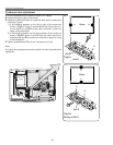
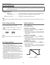
1. Receive the 1 dot black & white pattern computer sig-
nal.
2. Set to COMPUTER mode.
3. Enter the service mode.
[G-COMMON CENTER ADJUSTMENT]
4. Project only green light component to the screen.
5. Select group no. “3”, item no. “8” and change data
value to obtain the minimum flicker on the screen.
[B-COMMON CENTER ADJUSTMENT]
6. Project only blue light component to the screen.
7. Select group no. “3”, item no. “9” and change data
value to obtain the minimum flicker on the screen.
[R-COMMON CENTER ADJUSTMENT]
8. Project only red light component to the screen.
9. Select group no. “3”, item no. “10” and change data
value to obtain the minimum flicker on the screen.
Gamma Shift adjustment
Common Center adjustment
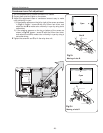
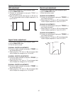
1. Receive the 16-step gray scale video signal.
2. Set to VIDEO mode.
3. Enter the service mode.
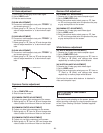
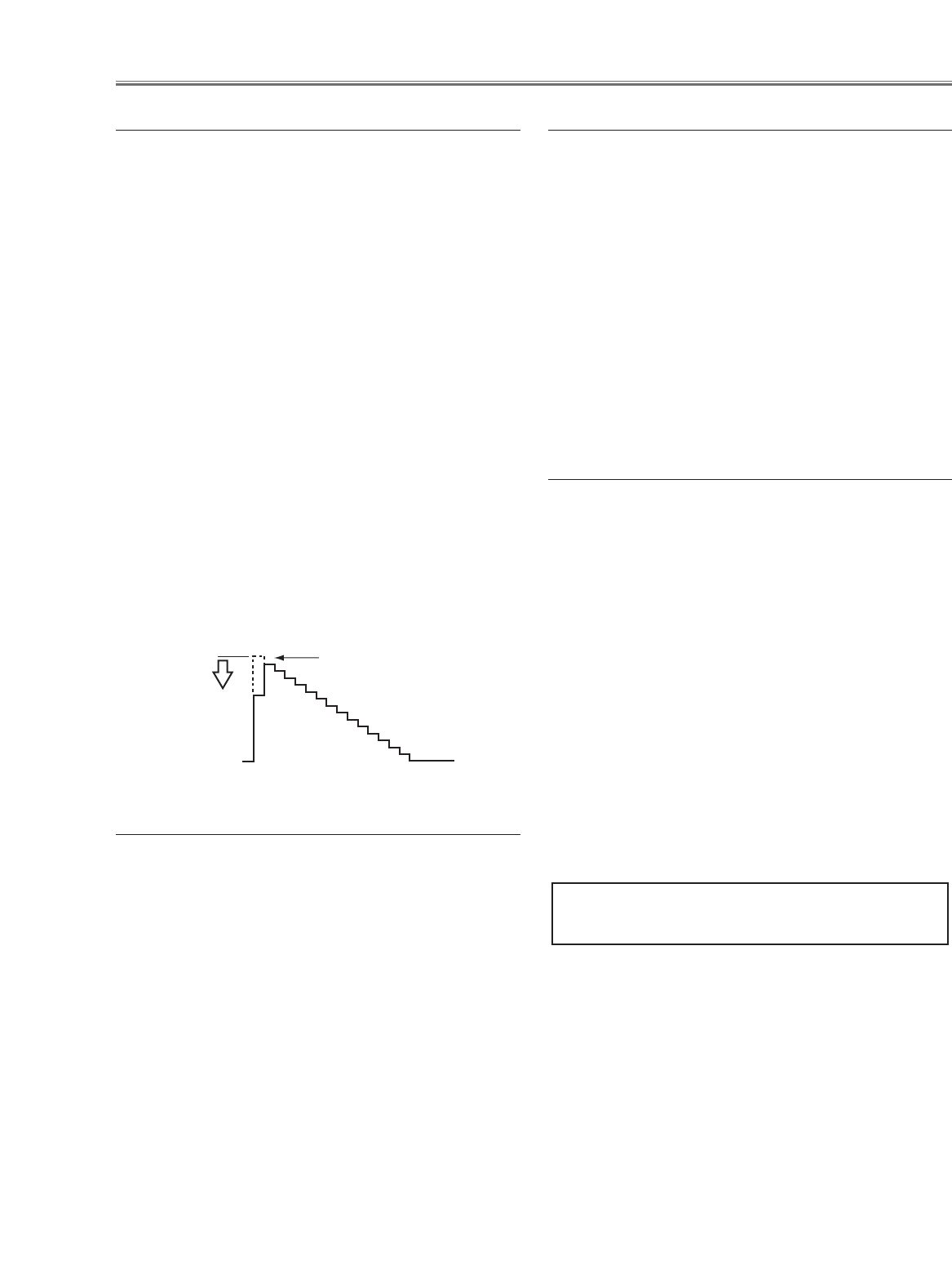
[R-GAIN ADJUSTMENT]
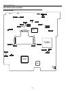
4. Connect an oscilloscope to test point “TP25R1”(+)
and chassis ground (-).
5. Select group no. “2”, item no. “3” and change data
value to adjust waveform “a” to be minimum ampli-
tude.
[G-GAIN ADJUSTMENT]
6. Connect an oscilloscope to test point “TP25G1”(+)
and chassis ground (-).
7. Select group no. “2”, item no. “4” and change data
value to adjust waveform “a” to be minimum ampli-
tude.
[B-GAIN ADJUSTMENT]
8. Connect an oscilloscope to test point “TP25B1”(+)
and chassis ground (-).
9. Select group no. “2”, item no. “5” and change data
value to adjust waveform “a” to be minimum ampli-
tude.
White Level
(a)
AV Gain adjustment
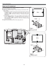
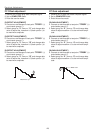
[PC WHITE BALANCE ADJUSTMENT]
1. Receive the 16-step gray scale computer signal.
2. Set to COMPUTER mode.
3. Enter the service mode, select group no. “2”, item no.
“7” (Red) or “8” (Blue), and change data values
respectively to make a proper white balance.
[AV WHITE BALANCE ADJUSTMENT]
4. Receive the 16-step grey scale video signal.
5. Set to VIDEO mode.
6. Enter the service mode, select group no. “2”, item no.
“7” (Red) or “8” (Blue), and change data values
respectively to make a proper white balance.
Confirm that the same white balance is obtained in
video and computer input.
White Balance adjustment
If you find the color shading on the screen, please
adjust the white uniformity by using the proper comput-
er and “Color Shading Correction” software supplied
separately.
NOTE ON WHITE UNIFORMITY
ADJUSTMENT