15D1
TOUCHCOMPUTER USER GUIDE 19
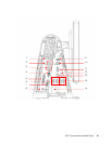
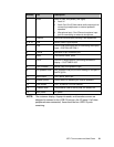
Number Port Description
1 Audio Audio in (left), out (center), mic (right)
• Audio In
• Audio Out: One 3.5mm stereo audio output jack for
connecting headphones or external powered
speakers
• Microphone Input: One 3.5mm microphone input
jack for connecting an external microphone
2 Ethernet One RJ45 Ethernet port providing LAN capabilities
3, 9, 10 USB Seven USB 2.0 type A ports
4 VGA One D-SUB VGA output port for connecting the display
head – SYSTEM USE ONLY
5 Parallel Standard 25-pin connector port
6 Serial Two USB-to-Serial ports
7 DVI-D One DVI-D output port for connecting the second
display – CUSTOMER USE
8 PS/2 universal Mouse (left) and keyboard (right)
9 24V powered USB 24V powered USB port; the max loading on this port is
24VDC @ 2A
11 Native serial One “native” serial port
12 Speaker power Power switch for disabling the internal speakers
13 Cash drawer RJ11, 6 position (12V/24V default)
14 Powered serial Two powered USB-to-Serial ports, 5V default/12V
15 Main power AC power
NOTE: The customer display, fingerprint reader, and barcode scanner are
designed to connect to the USB 2.0 ports on the I/O panel. If all three
peripherals were connected, there would be four USB 2.0 ports
remaining.


