


Operation
100
10.9 APM Procedure from Parallel Inverter Operation to Wrap-Around Bypass
Note: MBB is OPEN.
1. Turn OFF the Inverter on UPS1.
2. Turn OFF the Inverter on UPS2.
3. Verify that each UPS is now in Static Bypass Mode.
4. Open Battery Breaker(s) for UPS1.
5. Open Battery Breaker(s) for UPS2.
6. Verify that the Battery Status Light on UPS1 and UPS2 turns Red.
7. Close MBB - Bypass Breaker for System.
8. Open UIB1.
9. Open MOB1.
10. Verify that UPS1 is now completely OFFLINE.
11. Open UIB2.
12. Open MOB2.
13. Verify that UPS2 is now completely OFFLINE.
10.10 APM Procedure from Wrap-Around Bypass to Parallel Inverter Operation
Note: MBB is CLOSED.
1. Close UIB1 - Feed breaker to UPS1.
2. Close UIB2 - Feed breaker to UPS2.
3. Allow each UPS to qualify the Input and Bypass Feeds.
4. Close Battery Breaker(s) for UPS1.
5. Close Battery Breaker(s) for UPS2.
6. Close MOB1 - Output Breaker for UPS1.
7. Close MOB2 - Output Breaker for UPS2.
8. Verify that each UPS is now registering that it is in Static Bypass Mode and that the Battery
Status Light is not lit.
9. Open MBB.
10. Both UPS units should now be in static bypass mode.
11. Engage the Inverter on UPS1.
12. Engage the Inverter on UPS2.
13. Verify that there is a successful transfer from Static Bypass to Inverter (Normal Mode).
14. UPS1 and UPS2 are now both ONLINE.
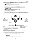
10.11 Emergency Shutdown With EPO
This circuit has been designed to switch off the UPS in emergency conditions (i.e., fire, flood, etc.). The
system will turn off the rectifier, inverter and stop powering the load immediately (including the
inverter and bypass), and the battery stops charging or discharging.
If the input utility is present, the UPS’s controls will remain active; however, the output will be
turned off. To remove all power from the UPS, the external feeder breaker should be opened.