


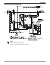
Installation Drawings
52
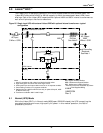
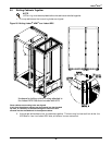
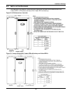
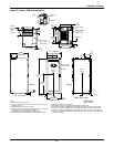
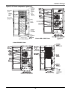
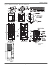
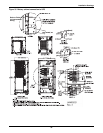
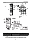
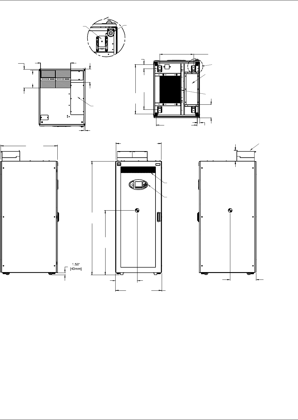
Figure 32 Liebert APM with top fan kit
Notes
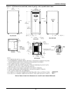
1. All dimensions are in inches (mm).
2. 24" (610) minimum clearance above unit and 36" (914) front access
required for service.
3. Keep cabinet within 15 degrees of vertical.
4. Top and bottom cable entry available through removable access plates.
Remove, punch to suit conduit size and replace.
5. Unit bottom is structurally adequate for forklift handling.
6. Control wiring and power wiring must be run in separate conduits.
UAM0212A
Pg. 1, Rev. 1
Caster
Mechanical
Stop
DETAIL A
Top Fan
Flange to
Flange
13.2"
(335mm)
12.1"
(308mm)
20.7" (526mm)
9.2"
(235mm)
0.8"
(21mm)
07.6"
(194mm)
Top
Fan
Power Cable
Entry 21.26" x 7.87"
(540x 200mm)
TOP VIEW
78.7"
(2000mm)
31.8"
(808mm)
FRONT
OVERALL
FRONT VIEW
RIGHT SIDE VIEW
LEFT SIDE VIEW
BOTTOM VIEW
FRONT
FRONT
Dim. Y
See Pg. 2
Dimension
X
Dimension Z
Display
Center of
Gravity
Center of
Gravity
Vent Screen
Front and Back
See Pg. 2
See Pg. 2
3"
(77mm)
23.4"
(595mm)
See Detail A
28.3"
(718mm)
Bracket
Centers
34.3"
(871mm)
1.4"
(36mm)
8.9"
(226mm)
28.3" (719mm)
Vent Screen
Power Cable Entry
21.26" x 7.87
(540mm x 200)
31.5" (800mm)
w/o Side Panels
39.5"
(1000mm)
7. Only copper cables are recommended.
8. All wiring is to be in accordance with nationaland local electrical codes.
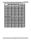
9. See Pg. 2 of 5 drawing: UAM02012B for weight table and centers of gravity for UPS at 208V.
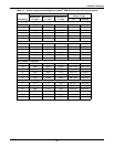
10. See Pg. 3 of 5 drawing: UAM02012C for weight table and centers of gravity for UPS at 480 V.
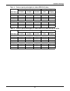
11. See Pg. 4 of 5 drawing: UAM02012D for weight table and centers of gravity for UPS at 600 V.
12. See Pg. 5 of 5 drawing: UAM02012E for weight table and centers of gravity for UPS with internal
maintenance bypass.