


Installation
15
The Fault LED will illuminate red when the Liebert FlexPower assembly has a problem.
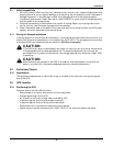
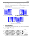
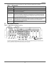
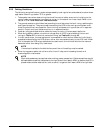
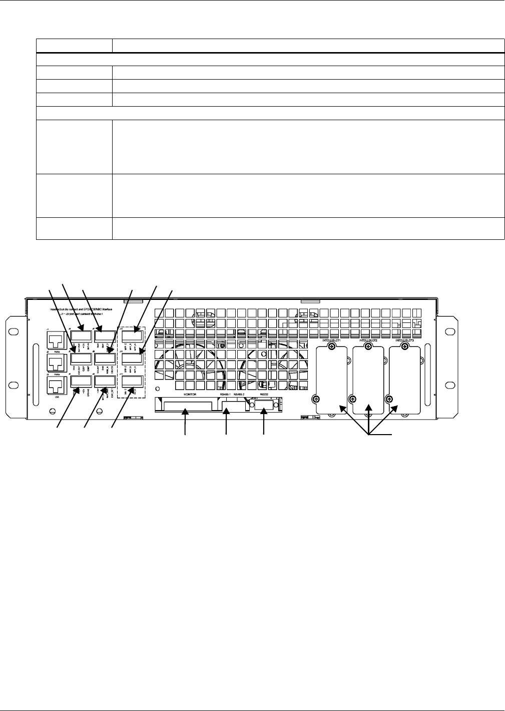
2.9 Static Bypass Assembly
Figure 3 Static bypass assembly connections
The Static bypass assembly has three Liebert IntelliSlot interface card bays and connections for
ancillary cabinets (Liebert BDC and battery) and for options.
Table 4 LED indications
LED Status Indication
Run LED (Green)
Flashing Green The inverter is starting, but has no output yet.
Constant Green The inverter has started to supply power.
OFF The inverter has not started up.
Fault LED (Red)
Constant Red
Auxiliary power failure (15V or 24V), rectifier overtemperature, rectifier failure (including battery
SCR short circuit), battery converter failure, soft start failure, main circuit back feed, abnormal
input current, inverter failure, output short circuit, bypass SCR short circuit fault, inverter relay
short circuit fault, abnormal bus voltage under non-sleep mode, module not ready, module ID
out of range and duplicated module ID.
Flashing Red
Charger failure, abnormal main circuit voltage, abnormal main circuit frequency, main circuit
undervoltage, main circuit reverse phase, battery unavailable, reverse battery, input zero-loss,
current sharing failure, module overload, inverter relay disconnection fault, bypass SCR
disconnection fault and input fuse blown.
OFF No above failures or alarms.
J10
J7J5
J6
J8
J9
RS-232
Liebert IntelliSlot
Bays 1, 2, 3
RS-485
J4
J11
J12
Monitor