


Maintenance
115
12.3 Detecting Trouble
It is important that the operator check the instrument readings if abnormal equipment performance
is suspected. Any metered value that differs appreciably from normal could mean an impending
malfunction, and should be investigated.
Items to check on the various UPS display screens include:
1. Output voltage of all phases should be within 2% of normal voltage. Output currents on each
phase should not normally differ by more than 20%. If a greater difference is noted, the load is
unbalanced and corrective action should be taken to redistribute the load, if possible.
2. If the UPS has not operated on battery power during the last 10 hours, the batteries should
require little charging current. Battery mimic should indicate normal DC voltage with relatively
little battery charge current.
3. Input current on each phase should be within 10% of the average input current. Alarm messages
indicate malfunction or impending malfunction. A daily check of the Operator Control Panel will
help to provide an early detection of problems. Refer to Appendix B - UPS Status Messages to
interpret alarm messages.
4. Tracing a problem to a particular section is facilitated by alarm messages and the metered
parameter indications. These are stored in the Status Reports and can be displayed at the
Operator Control Panel or at an optional terminal.
12.4 Reporting a Problem
If a problem occurs within the UPS, review all alarm messages along with other pertinent data. This
information should be given via telephone to the Liebert Service dispatcher. This information can also
be automatically sent by telephone modem. Call 1-800-LIEBERT to report a problem or to request
assistance.
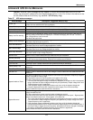
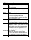
12.5 Corrective Actions
For each alarm message on the Operator Control Panel and the Remote Alarm Status Panel, you can
find the recommended corrective action in Appendix B - UPS Status Messages.
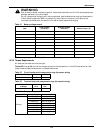
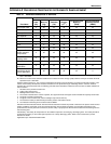
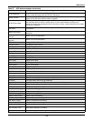
12.6 Recommended Test Equipment
A list of recommended test equipment and tools required to maintain, troubleshoot, and repair the
UPS module is given in Table 55. You may substitute instruments of equivalent range and accuracy.
All instruments should be calibrated and be within the current calibration cycle. Calibration data for
the instruments should be maintained in equipment-history files and the instruments labeled for
audit and verification.
NOTE
If the UPS system has a blown fuse, the cause should be determined before you replace the fuse.
Contact Liebert Global Services.
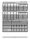
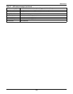
Table 55 Recommended test equipment and tools
Qty Test Equipment Manufacturer Model or Type
1 Oscilloscope Tektronix, H-P or Fluke DC to 50 MHz
2 Voltage Probes Tektronix, H-P or Fluke 10X, with 10 ft. Cable
2 Voltage Probes Tektronix, H-P or Fluke 100X, with 10 ft. Cable
1 Digital Multi-meter Fluke 8060, with Test Leads
1 Tool Kit N/A Standard electrical contractor tools