


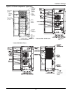
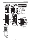
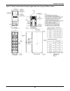
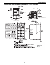
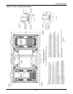
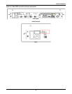
Installation Drawings
64
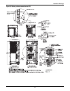
See Figure 27 and Table 11 for additional details.
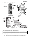
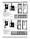
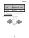
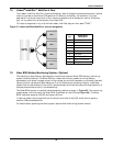
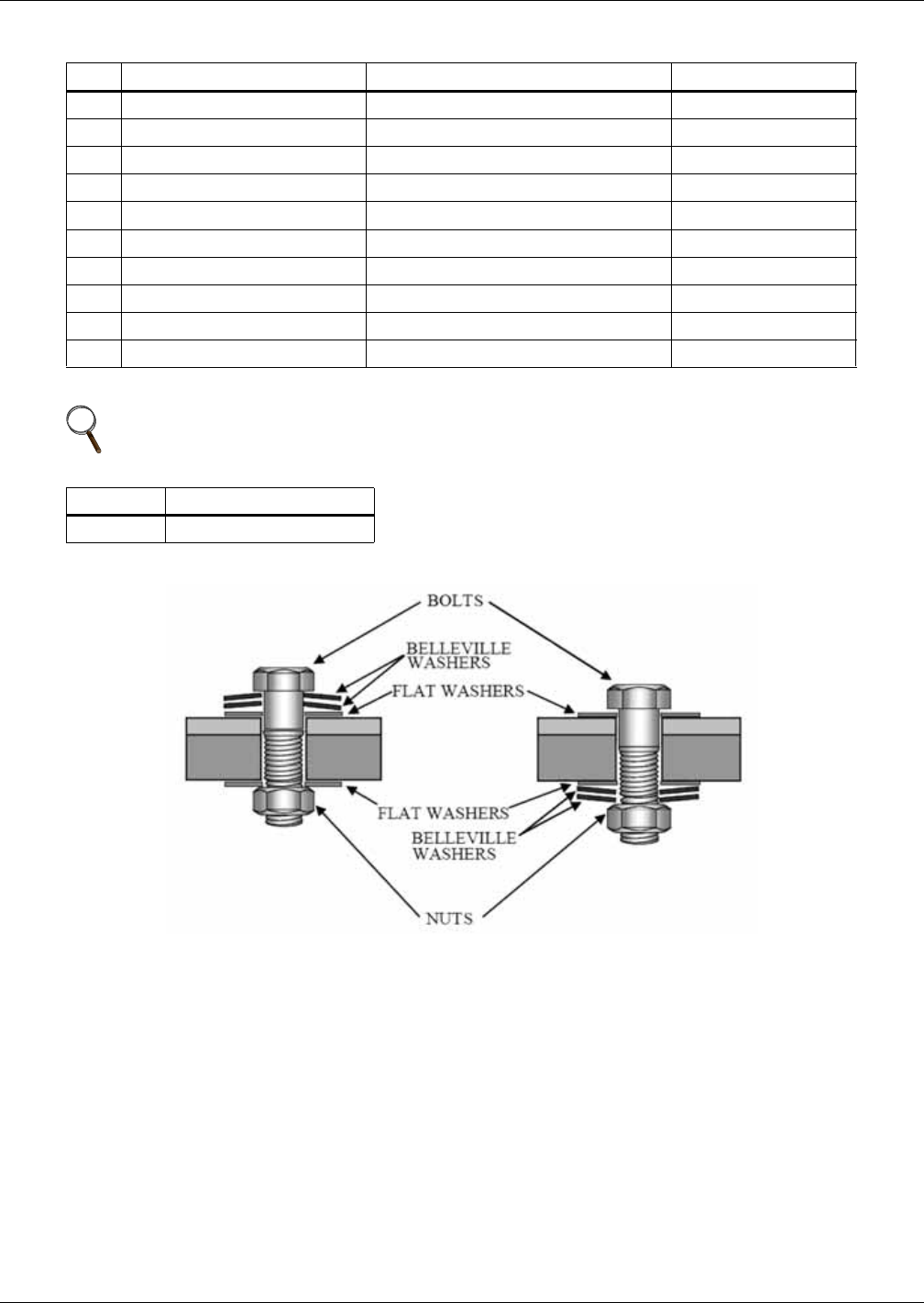
Figure 42 Acceptable hardware configuration for torque application
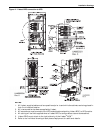
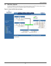
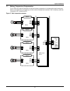
Table 17 Interconnect wiring for Liebert APM to Liebert BDC
Run
From To Conductors
A Utility AC source BDC System Input Bus Phase A, B, C
B Utility AC Source BDC System Input Bus Neutral
C BDC Bypass Isolation Breaker UPS Main Input Phase A, B, C
D BDC Bypass Isolation Breaker UPS Main Input Neutral
E UPS Output MBC Maintenance Isolation Breaker Phase A, B, C
F UPS Output MBC Maintenance Isolation Breaker Neutral
G BDC Panelboard Load AC Connection Phase A, B, C
H BDC Panelboard Load AC Connection Neutral
I Utility AC Source All Ground Connections Ground
J BDC Terminal Block TB1 UPS Static Bypass Module J5 and J12 Wiring for KO on MBC
NOTE
Wiring is supplied when the UPS and Liebert BDC are ordered as a system.
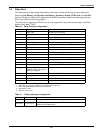
Table 18 Spring washer torque application
Hardware Two Belleville Washers
M10 (3/8") 240 lb-in. (27 N-m)