


Operation
74
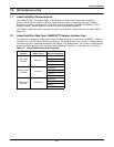
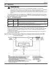
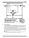
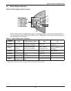
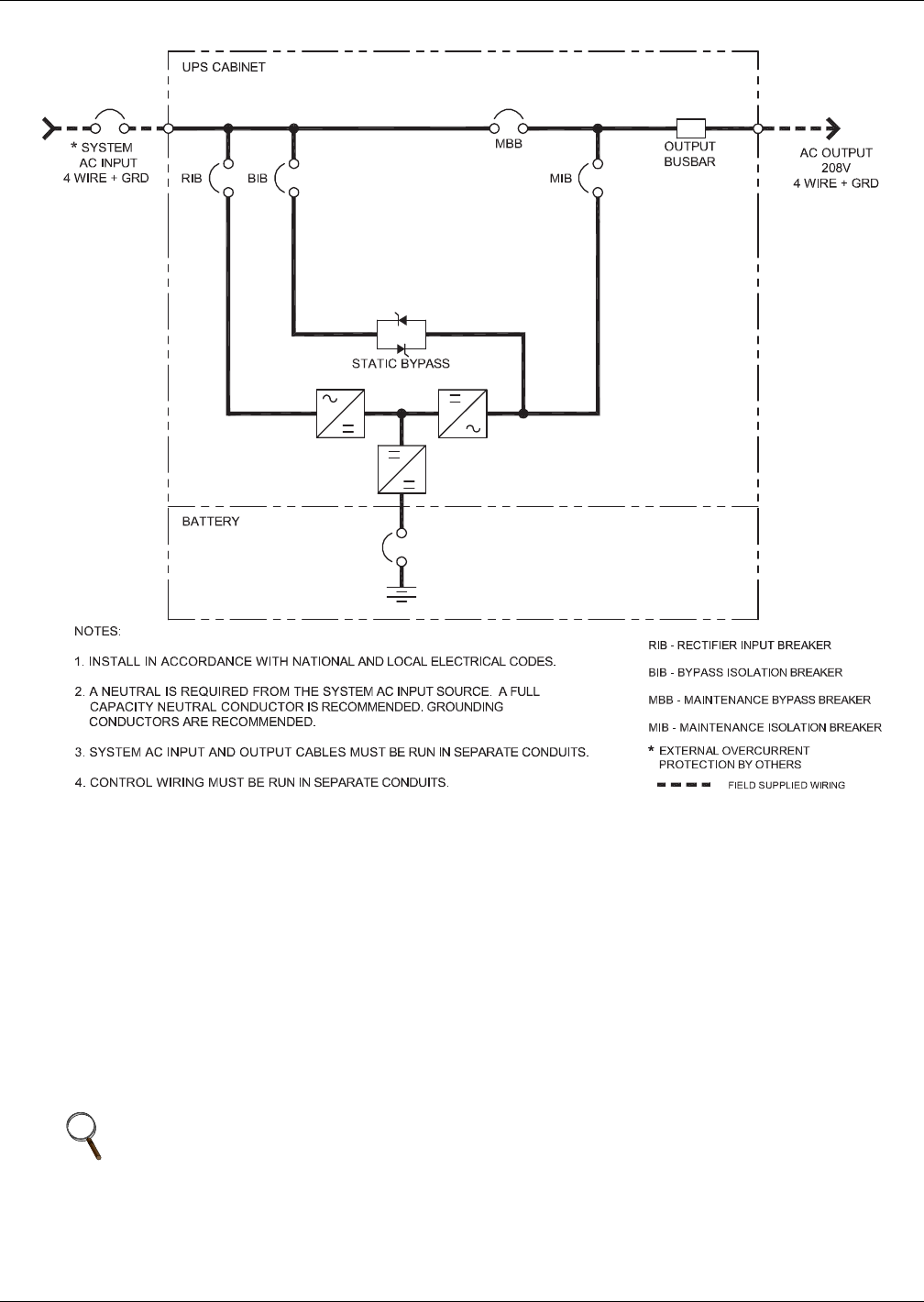
Figure 50 Block diagram—Single input configuration with four-breaker internal bypass
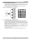
8.1 Static Bypass Switch
The circuit block labeled “Static Bypass” in Figure 48 contains an electronically controlled switching
circuit that enables the critical load to be connected to either the inverter output or to a bypass power
source via the static bypass line. During normal system operation, the load is connected to the
inverter and the inverter contactor is closed; but in the event of a UPS overload or inverter failure,
the load is automatically transferred to the static bypass line.
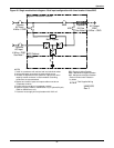
To provide a clean (no-break) load transfer between the inverter output and static bypass line, the
static switch activates, connecting the load to bypass. To achieve this, the inverter output and bypass
supply must be fully synchronized during normal operating conditions. This is achieved through the
inverter control electronics, which make the inverter frequency track that of the static bypass supply,
provided that the bypass remains within an acceptable frequency window.
NOTE
When the UPS is operating in static bypass mode or on maintenance bypass, the connected
equipment is not protected from power failures or surges and sags.
UAM01070
Rev. 2