Connectivity Module Installation 1-2
How to Install the Connectivity Module for
a stand-alone Power Manager or Digital
Power Meter
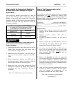
The Connectivity Module (CM) mounts on a DIN rail
near the Power Manager (PM) or Digital Power Meter
(DPM). A long serial cable connects the Connectivity
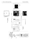
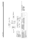
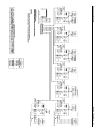
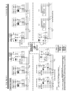
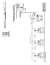
Module to the PM or DPM. Refer to installation drawings
provided and follow the steps below to install the
Connectivity Module.
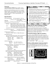
Connectivity Module Kit K889958
for a stand-alone Power Manager or Digital
Power Meter (not connected to an ATS)
Connectivity
Module 5150
629800-004
DIN Rail and
Hardware
754610
4 ft. Serial Cable
for PM or DPM
629798-002
To avoid possible shock, burns, or death, deenergize all
electrical sources to the ATS before installing the
Connectivity Module.
1. De-energize the power source that feeds the PM (or
DPM). Open enclosure door and check with a
non-contact AC voltage detector.
2. Mount the DIN rail (supplied in the kit) onto two
studs (on the door) below or adjacent to the PM or
DPM.
3. Install Connectivity Module onto DIN rail by
hooking the bottom of module on bottom of DIN rail
and rocking it upward unit it snaps in place.
4. Install the 4-foot serial cable between the Power
Manager J5 receptacle (or Digital Power Meter J2
receptacle) and the Connectivity Module J2
receptacle.
Now test communications (go to next column).
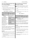
How to Test Communication to the
Connectivity Module
You need the following settings from your network
administrator for each
Connectivity Module (CM)
connected to an Automatic Transfer Switch (ATS), Power
Manager (PM), or Digital Power Meter (DPM). Fill in the
form provided in the Appendix:
IP Address: ______________ (unique for each module)
Subnet mask __________ (usually same for all modules)
Gateway: ________________________ (usually blank)
Required items:
• Portable laptop computer with network card, running
Windows Xp and Windows Internet Explorer 6.0 +
installed.
• Ethernet crossover network cable (part no.
629590-006).
• Connectivity Module connected to the ATS, PM, or
DPM.
1. Directly connect the specified Ethernet crossover
cable between your laptop’s Ethernet jack and the
deenergized Connectivity Module jack J3.
2. For safety, close the ATS, PM, or DPM enclosure
door as far as possible (with the crossover cable
running to the laptop computer outside
the enclosure).
Then energize ATS, PM, or DPM and the
Connectivity Module.
3. Refer to the Appendix and select the appropriate
TCP/IP Installation & Configuration instructions for
your laptop computer’s operating system. This
procedure sets up your laptop computer (if necessary)
for network connections and tests communications to
the Connectivity Module.
4. After you have confirmed communication with the
Connectivity Module, continue to the next page to
view and change the configuration of the
Connectivity Module and ATS, PM, or DPM.
Now view and change the configuration
(go to page 1-3)
DANGER
!


