


4-2 ASCO 940/962 ATSs Connectivity Module
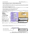
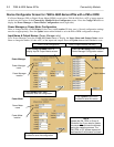
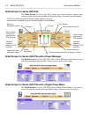
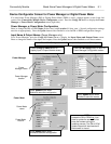
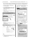
Detail Screen for ASCO 940/962 ATSs
The Detail Screen for ASCO 940/962 ATSs shows the switch location,
ratings, timer settings, actual timer values, pickup and dropout settings, and
other status indications.
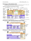
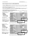
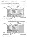
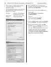
Detail Screen for ASCO 940/962 ATSs with a Power Manager
The Detail Screen for ASCO 940/962 ATSs shows the switch location,
ratings, timer settings, actual timer values, pickup and dropout settings, and
other status indications.
Actual voltage
reading from
A
TS controller.
Load connected to Normal or Emer
g
enc
y
Source
A
TS ratin
g
s
Status of Normal SourceATS name
Voltage &
frequency
settings in ATS
controller.
Status of
Emergency
Source
Actual voltage
reading from
ATS controller.
Voltage &
frequency
settings in ATS
controller.
ATS one-line icon shows position & source status
(green or red circle means source is acceptable,
grey circle means source is not acceptable)
Time delay
settings in
ATS
controller.
Time delay
settings in
ATS
controller.
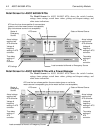
Actual voltage
reading from
A
TS controller.
Load connected to Normal or Emergency Source
Status of Normal SourceATS name
Voltage &
frequency
settings in ATS
controller.
Status of
Emergency
Source
Actual voltage
reading from
ATS controller.
Voltage &
frequency
settings in ATS
controller.
Time delay
settings in
ATS
controller.
Time delay
settings in
ATS
controller.
ATS one-line icon shows position & source status (green or red circle
means source is acce
p
table
,
g
re
y
circle means source is not acce
p
table
)