Functional Description
6806800H60A AMC-S402 Installation and Use 10
MUX
Po w er
Reg u l at or
| | || || ||||| || |||||||||| | |||||||| ||| || ||||||||
80221 -12-04-2007MFB 6635 NTCZ010
Pow er
Regul at or
MMC
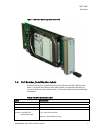
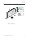
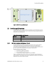
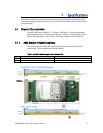
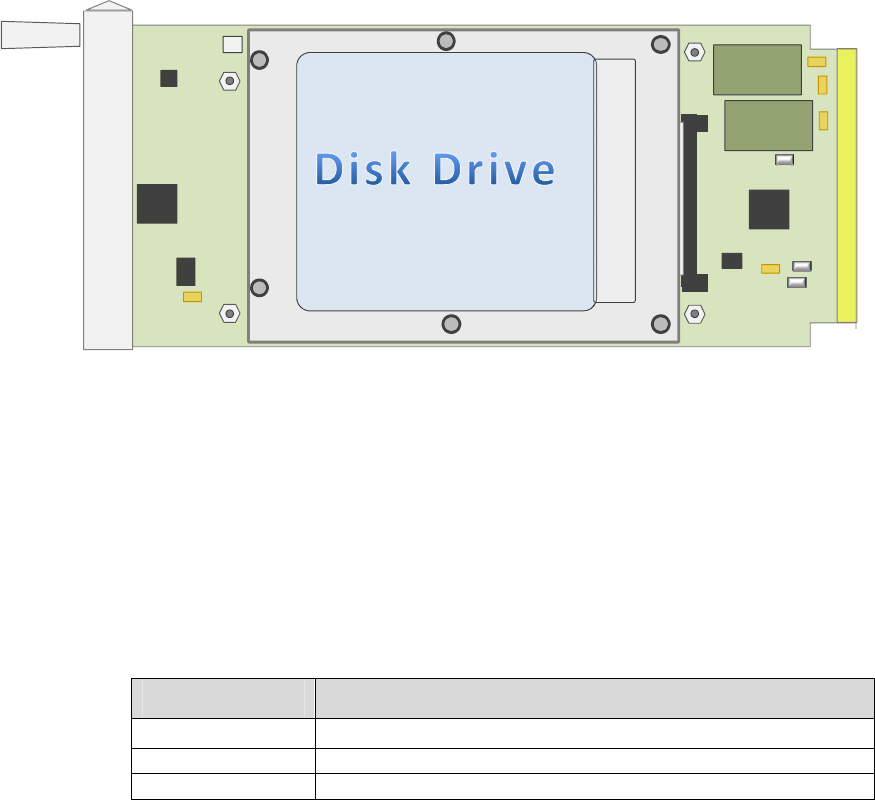
Figure 5. AMC-S402 Top Level Board Layout
3.3 Serial Storage I/O Interfaces
The AMC-S402 modules plug into ATCA carrier blades and uTCA backplanes which
support AMC.3 storage signaling. Port 2 is wired to the SAS primary port and Port 3
is wired the SAS secondary port.
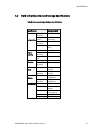
Table 4 I/O Ports Available On AMC Connector
AMC I/O Description
Port 2 3Gb SAS Receive and transmit pairs, Primary port
Port 3 3Gb SAS Receive and transmit pairs, Secondary port
MMC device Serial IPMI management bus
3.3.1 SAS Port Isolation Multiplexor Circuit
The AMC-S402 includes SAS re-transmitter circuits that can be used to adjust or
“wave-shape” the transmit signal characteristics driven out the AMC finger
connections (storage signaling ports 2 and 3). At manufacturing time, this circuit is
pre-set to values that are optimal for the majority of deployments.
Programmable parameters include:
transmit pre-emphasis (five levels)
receiver equalization (three levels)
Transmit output swing to support SAS up to 1600mV
Tools are available to adjust these circuits to accommodate atypical backplane or
cable situations. Please contact your Emerson applications engineer if you feel your
deployment will require different settings.


