


Electrical Specifications
15
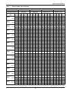
CW106
20.0 HP
(Upflow only)
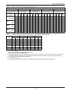
FLA 165.1 154.8 77.7 63.7 86.0 76.2 38.6 33.6 138.5 132.6 66.1 52.1 59.4 54.0 27.0 22.0
WSA 206.4 193.5 97.1 79.6 107.5 95.3 48.3 42.0 173.1 165.8 82.6 65.1 74.3 67.5 33.8 27.5
MFCB 225 200 110 90 150 125 70 60 200 200 90 70 125 110 60 45
CW114
10.0 HP
FLA 136.5 128.8 64.7 52.7 57.4 50.2 25.6 22.6 109.9 106.6 53.1 41.1 30.8 28.0 14.0 11.0
WSA 170.6 161.0 80.9 65.9 71.8 62.8 32.0 28.3 137.4 133.3 66.4 51.4 38.5 35.0 17.5 13.8
MFCB 175 150 80 60 90 80 40 35 125 125 70 50 60 60 30 20
CW114
15.0 HP
FLA 151.9 142.8 71.7 58.7 72.8 64.2 32.6 28.6 125.3 120.6 60.1 47.1 46.2 42.0 21.0 17.0
WSA 189.9 178.5 89.6 73.4 91.0 80.3 40.8 35.8 156.6 150.8 75.1 58.9 57.8 52.5 26.3 21.3
MFCB 200 175 90 70 125 110 50 45 175 150 80 60 100 90 45 35
CW114
20.0 HP
(Upflow only)
FLA 165.1 154.8 77.7 63.7 86.0 76.2 38.6 33.6 138.5 132.6 66.1 52.1 59.4 54.0 27.0 22.0
WSA 206.4 193.5 97.1 79.6 107.5 95.3 48.3 42.0 173.1 165.8 82.6 65.1 74.3 67.5 33.8 27.5
MFCB 225 200 110 90 150 125 70 60 200 200 90 70 125 110 60 45
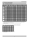
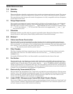
Table 8 Indoor evaporator fan motor electrical requirements—60Hz systems
Hp
208 230 460 575
FLA LRA FLA LRA FLA LRA FLA LRA
2.0 HP 7.5 46.9 6.8 40.8 3.4 20.4 2.7 16.2
3.0 HP 10.6 66.0 9.6 58.0 4.8 26.8 3.9 23.4
5.0 HP 16.7 105.0 15.2 91.0 7.6 45.6 6.1 36.6
7.5 HP 24.2 152.0 22.0 132.0 11.0 66.0 9.0 54.0
10.0 HP 30.8 193.0 28.0 168.0 14.0 84.0 11.0 66.0
15.0 HP 46.2 290.0 42.0 252.0 21.0 126.0 17.0 102.0
20.0 HP 59.4 321.0 54.0 290.0 72.0 145.0 22.0 116.0
1. Refer to General Data Section for standard fan motor size on units.
2. FLA = FulL Load Amps
WSA = Wire Sizing Amps (Minimum supply circuit ampacity)
MFCB = Maximum Fuse or Circuit Breaker Size
3. Amperage requirements are based on the rated max FLA current of each component in the unit. The rated max FLA current of the unit
is not the sum total of all components, but is the total of the components which operate during maximum electrical load conditions.
4. The values in the chart are for power of the unit only.
5. Units are 3 phase, 60 cycle.
6. For units with other variations not listed above, consult factory engineering department for electrical requirements.
Table 7 Electrical data—60 Hz Systems (continued)
Chilled Water Models - 60Hz
Reheat Options Electric None Electric Electric
Humidifier Options
Infrared or Steam
Generating
Infrared or Steam
Generating Steam or None Steam or None
Models / Motor
HP Volts 208 230 460 575 208 230 460 575 208 230 460 575 208 230 460 575