i
TABLE OF CONTENTS
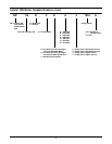
LIEBERT CW MODEL NUMBER NOMENCLATURE . . . . . . . . . . . . . . . . . . . . . . INSIDE FRONT COVER
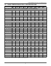
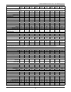
1.0 LIEBERT CW PERFORMANCE DATA—50 & 60 HZ SYSTEMS . . . . . . . . . . . . . . . . . . . . . . . .2
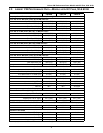
2.0 LIEBERT CW PERFORMANCE DATA—MODELS WITH EC FANS, 50 & 60 HZ . . . . . . . . . . . .4
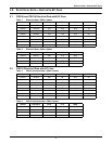
3.0 ELECTRICAL DATA—UNITS WITH EC FANS . . . . . . . . . . . . . . . . . . . . . . . . . . . . . . . . . . . . .5
3.1 CW106 and CW114 Electrical Data with EC Fans . . . . . . . . . . . . . . . . . . . . . . . . . . . . . . . . . 5
3.2 CW181 Electrical Data with EC Fans. . . . . . . . . . . . . . . . . . . . . . . . . . . . . . . . . . . . . . . . . . . . 5
4.0 DIMENSIONAL DATA . . . . . . . . . . . . . . . . . . . . . . . . . . . . . . . . . . . . . . . . . . . . . . . . . . . . . .6
5.0 UPFLOW DUCT CONNECTION DATA CW026—CW084 . . . . . . . . . . . . . . . . . . . . . . . . . . . 11
6.0 BLOWER DUCT & DECK DIMENSIONS, CW106 AND CW114, UPFLOW MODELS. . . . . . . . .12
7.0 ELECTRICAL SPECIFICATIONS . . . . . . . . . . . . . . . . . . . . . . . . . . . . . . . . . . . . . . . . . . . . . .13
8.0 GUIDE SPECIFICATIONS . . . . . . . . . . . . . . . . . . . . . . . . . . . . . . . . . . . . . . . . . . . . . . . . . .16
FIGURES
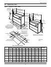
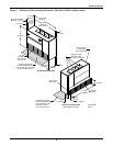
Figure 1 Dimensions, CW026 - CW084. . . . . . . . . . . . . . . . . . . . . . . . . . . . . . . . . . . . . . . . . . . . . . . . . . . . . . . 6
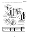
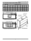
Figure 2 Dimensional Data—50 & 60 Hz Systems CW106—CW114, downflow models. . . . . . . . . . . . . . . . 7
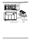
Figure 3 Cabinet and Floor Planning Dimensional Data, Downflow Model CW181 with EC Fans . . . . . . . 8
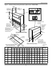
Figure 4 Cabinet and floor planning dimensions, upflow models—CW026-CW084 . . . . . . . . . . . . . . . . . . . 9
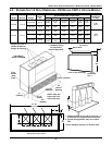
Figure 5 Cabinet and floor planning dimensions, CW 106 and CW114 upflow models. . . . . . . . . . . . . . . . 10
TABLES
Table 1 Electrical data—60Hz-3 phase. . . . . . . . . . . . . . . . . . . . . . . . . . . . . . . . . . . . . . . . . . . . . . . . . . . . . . 5
Table 2 Electrical data—50Hz-3 phase. . . . . . . . . . . . . . . . . . . . . . . . . . . . . . . . . . . . . . . . . . . . . . . . . . . . . . 5
Table 3 CW181 electrical data—60Hz-3 phase. . . . . . . . . . . . . . . . . . . . . . . . . . . . . . . . . . . . . . . . . . . . . . . . 5
Table 4 CW181 electrical data—50Hz-3 phase. . . . . . . . . . . . . . . . . . . . . . . . . . . . . . . . . . . . . . . . . . . . . . . . 5
Table 5 Electrical data—50 Hz systems . . . . . . . . . . . . . . . . . . . . . . . . . . . . . . . . . . . . . . . . . . . . . . . . . . . . 13
Table 6 Indoor evaporator fan motor electrical requirements—50Hz systems . . . . . . . . . . . . . . . . . . . . . 13
Table 7 Electrical data—60 Hz Systems . . . . . . . . . . . . . . . . . . . . . . . . . . . . . . . . . . . . . . . . . . . . . . . . . . . . 14
Table 8 Indoor evaporator fan motor electrical requirements—60Hz systems . . . . . . . . . . . . . . . . . . . . . 15


