17
Installation
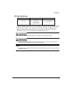
APS Input Specification
Using the APS supply input to power the drive logic and motor encoder allows the drive bus
to operate at DC voltages below 42 VAC (60 VDC bus). The drive will operate down to 12
VDC on the bus (10 VAC on L1 and L2). However the low DC bus monitoring must be
disabled to prevent faults at these low DC bus voltage levels. This can be done with
PowerTools software on the Advanced tab in Detailed Setup mode.
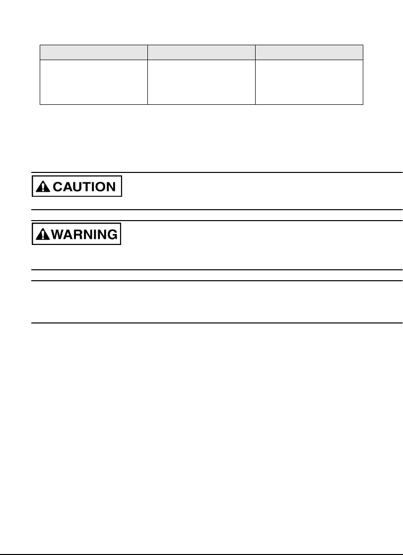
Do not wire AC line into the APS input. Doing so will damage the drive.
Do not open the APS jumper access panel until at least six minutes after the main AC
power has been removed from the L1 and L2 terminals.
Note
Connecting 24V common on the APS to chassis ground reduces offset voltage in Analog
Diagnostic Outputs.
Voltage Range Current Inrush Current
18-30 VDC
0.5 A maximum
0.7 A peak
( 0.4 A maximum
0.6 A peak if external
encoder is not used )
80 A for 1 ms if not limited by
power supply


