Installation and Configuration
13
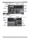
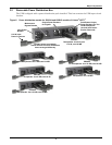
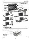
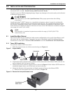
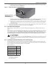
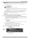
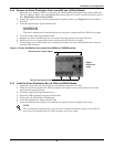
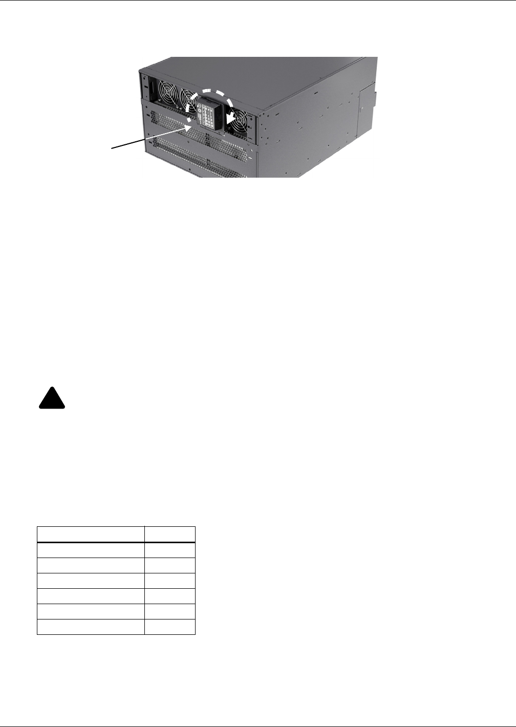
b. Pull the operation and display panel gently, rotate it 90 degrees clockwise and snap it back
into position, as shown in Figure 11.
Figure 11 Rotate the operation and display panel
c. Pull the logo on the front plastic bezel cover gently, rotate it 90 degrees clockwise and snap it
back into position. The rotated front plastic bezel cover is shown in Figure 11.
d. Replace the front plastic bezel cover on the Liebert
®
GXT3
™
. At this point, the UPS operation
and display panel and logo have been rotated 90 degrees clockwise, which provides upright
viewing for users.
5. Place the Liebert GXT3 and any battery cabinets on the support bases. Each Liebert GXT3 needs
two support assemblies, as shown in the lower half of Figure 1.
5.1.2 Rack-Mount UPS Installation
When using the Liebert GXT3 in a rack, the UPS must be supported by a slide kit, fixed rails or a
shelf.
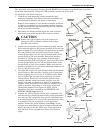
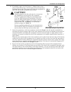
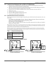
When using the optional Adjustable Rack Mount Kit, you will use the following instructions. The fig-
ures accompanying 5.1.3 - Installing the Adjustable Rack-Mount Kit—Sold Separately shows
the positioning of the rack-mounting brackets. Emerson recommends taking the internal batteries out
of the UPS during rack installation. This will make the UPS cabinet lighter and easier to handle.
5.1.3 Installing the Adjustable Rack-Mount Kit—Sold Separately
This kit contains parts needed to mount several different models of UPS and external battery cabi-
nets into EIA310-D standard four-post racks that are 18-32" deep (457-813mm). The weight limit per
pair of adjustable rack-mounting brackets is 91 kg (200lb).
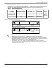
Parts included are:
Tools needed for installation are:
• one Phillips screwdriver
• one 7mm wrench
!
CAUTION
The Liebert GXT3 is heavy; see 12.0 - Specifications. The UPS must be installed as near the
bottom of a rack as possible. If placed too high, it can make the rack top-heavy and prone to
tipping over.
Item Quantity
Rear bracket members 2
Front bracket members 2
Inner bracket members 2
M4 machine screws 16
M4 locking hex nuts 8
M5 machine screws 8
Operation and Display
Panel Rotated
Clockwise 90 Degrees


