


Preparation
9
4.0 PREPARATION
These installation instructions provide all the information needed for positioning the Nfinity Mainte-
nance Bypass Cabinet (including environmental requirements) and for connecting the input and out-
put power cables.
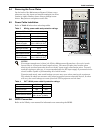
4.1 Inspection
Upon receiving the Nfinity Maintenance Bypass Cabinet, examine the packaging for any signs of mis-
handling or damage. If any damage is noted, contact your local dealer or Liebert representative and
notify your carrier.
4.2 Environment
The Maintenance Bypass Cabinet environment must be free of conductive contaminants and exces-
sive moisture (water condensation), flammable vapors, chemical fumes, or corrosive gases and liquids.
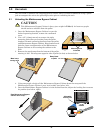
4.3 Required Setup Equipment
The tools below are required in order to properly setup your maintenance bypass cabinet:
•pallet jack
• 1/2" (13 mm) wrench
• torque wrench
• flat-head screwdriver
• #2 Phillips screwdriver
• 3/16" (5 mm) Allen wrench
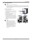
4.4 Site Preparation
When deciding where to locate your Maintenance Bypass Cabinet, consider the weight and size of the
unit. Make sure that the structural integrity of the floor can withstand the weight. Refer to the table
below for dimensional considerations:
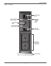
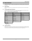
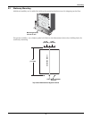
Check to make sure that your Maintenance Bypass Cabinet will be located in a well-ventilated area
with at least 12 inches (304mm) in front of and behind it. Transformer based models are forced air
cooled with the aid of two internal cooling fans.
Figure 5 Clearances
Table 2 Maintenance Bypass Cabinet physical data
Dimensions
Model With Transformer Without Transformer
W x D x H
In (mm)
9.5 x 26.5 x 30.4
(241.3 x 673.1 x 772.16)
Weight 287 lbs (130 kg) 85 lbs (38 kg)
12" (304mm)
12" (304mm)