Cable Installation
12
6.0 CABLE INSTALLATION
6.1 Wiring Preparation
Be sure that the unit is not connected to any AC mains power source or UPS before installing any wir-
ing to this unit. This Maintenance Bypass Cabinet should be installed by a qualified / certified electri-
cian.
6.2 Preparing Internal Wiring
The Maintenance Bypass Cabinet is factory-configured for single-source installations. If your installa-
tion requires dual-source capabilities, the Maintenance Bypass Cabinet’s wiring must be modified.
6.3 Dual Source Configuration
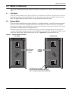
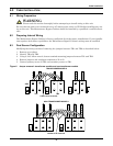
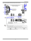
Modifying the wiring consists of removing the jumpers between TB1 and TB2 as described below:
1. Remove cover plates.
2. Identify TB1 and TB2.
3. Using a 3/16" Allen wrench, loosen terminal mounting jumpers between TB1 and TB2.
4. Remove jumpers and retighten terminals to 50 in-lb.
5. Connect primary source to TB2 and secondary source to TB1.
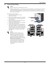
Figure 6 Jumper removal—transformer models and non-transformer models
!
WARNING
Please read this section thoroughly before attempting to install wiring to this unit.
TRANSFORMER MODELS
TB1 TB2 TB3
Cables to be removed
NON-TRANSFORMER MODELS
TB1 TB2
Cables to be removed
GEC


