


EMULEX MODEL 375 SAN STORAGE SWITCH
USER’S GUIDE CHAPTER 2: SWITCH INSTALLATION
EMULEX CORPORATION 11
P
ART NUMBER 00041392-002 REV. B
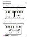
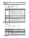
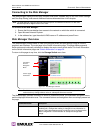
Power Supply/Fan Module LED
The switch uses two power supply/fan modules to guarantee high availability with failover. Each power
supply has a separate LED to indicate its condition.
When a power supply or fan fault occurs, the switch will continue to operate normally as long as the
faulty power supply/fan module remains installed in the switch and there are at least two fans
operational in each module. If the power supply/fan module is removed from the switch, the switch will
continue to operate normally for approximately 20-30 minutes. However, to guarantee continued
operation, the malfunctioning module should be immediately replaced to maintain high availability.
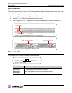
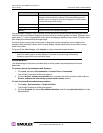
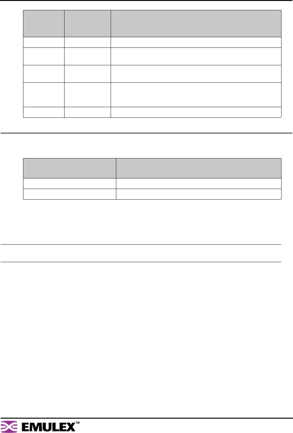
Flashing Off Activity. Data is being transferred between the port and device.
On Off Normal operation but no activity. Port and device are fully
operational.
On Flashing Manually bypassed. A port can be manually bypassed using the
Web Manager’s Bypass Port feature.
On On Bypassed. SFP is installed but the port is not receiving a valid
signal or is receiving an F8 Failure notification from the attached
device.
Flashing Flashing Beaconing. This is set manually using the Web Manager or CLI.
Power Supply/Fan Module LED
(green LED)
Indication
On No faults exist and AC power is supplied to the module.
Off A power supply or fan fault has occurred in the module.
Note: Keeping spare power supply/fan modules (Part Number 601319) in stock is highly recommended.
Contact a sales representative for further information.
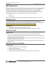
SFP Status
LED
(green LED)
Port Bypassed
LED
(yellow LED)
Indication