EMULEX MODEL 375 SAN STORAGE SWITCH
USER’S GUIDE CHAPTER 3: SWITCH MANAGEMENT
EMULEX CORPORATION 45
P
ART NUMBER 00041392-002 REV. B
Cascading Switches
When multiple switches are connected, the connecting links between the switches are referred to as
"cascades". There are two distinct cascade configurations to consider when configuring networks for
optimal performance and connectivity: string cascades and tree cascades.
String Cascades
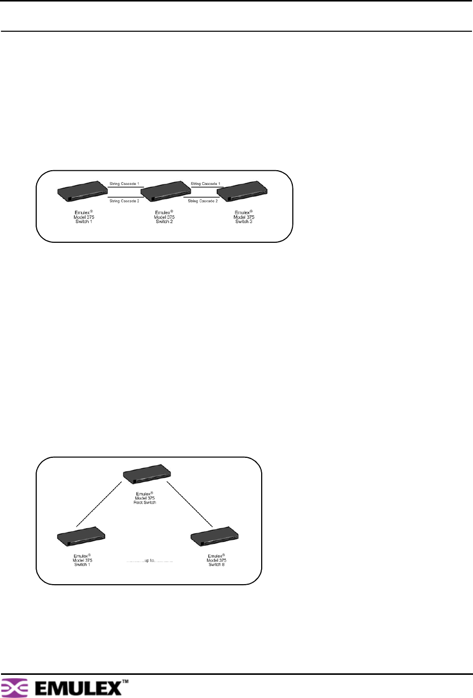
A string cascade connects multiple switches (up to three switches maximum) together in a "daisy-
chained" configuration. When one device requests access to another device, the request is sent to each
switch in the cascade before device access is granted. This arbitration method promotes fairness
between the switches. However, when compared to tree cascades, string cascades offer less
performance due to the increased latency between the switches.
When configuring a switch port for a string cascade, use the String Cascade Smart Setting. To enable
the string cascade, go to the Automatic Trunking page. From the Automatic Trunking page, select the
Single Cascade option, or place the string cascade into a trunk group. See “Automatic Trunking” on
page 46 for additional information.
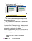
To reduce contention and improve performance between initiator traffic and target traffic when using a
string cascade configuration, connect the ports of each switch together using the same String Cascade
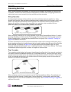
Smart Settings. For example, in Figure 3-20 the three switches are connected through two string
cascades using the String Cascade - Trunk 1 and String Cascade - Trunk 2 Smart Settings. This creates
two dedicated paths through which initiators and targets can communicate.
Tree Cascades
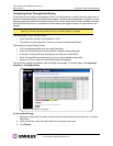
Tree cascades provide the best performance (lowest latency) configuration. A tree cascade consists of a
root switch connected to additional switches (up to 8 switches maximum). When a device on a switch
requests access to another device, the request is sent the particular switch for that device. The limitation
to the tree cascade configuration is the random nature of devices gaining access to one another, as
fairness is not used for tree cascades.
When configuring a port for a tree cascade, use the Tree Cascade Smart Setting. To enable the tree
cascade, go to the Automatic Trunking page. From the Automatic Trunking page, select the Single
Cascade option, or place the tree cascade into a trunk group. See “Automatic Trunking” on page 46 for
additional information.
Figure 3-20: String Cascade configuration example
Figure 3-21: Tree Cascade configuration example


