


Management Terminal Setup
2-2 Local Management Requirements
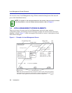
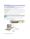
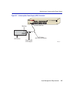
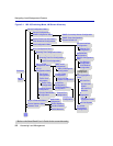
2.1.1 Console Cable Connection
Use the Console Cable Kit provided with the SmartSwitch device to attach the management
terminal to the SmartSwitch device COM port as shown in Figure 2-1.
To connect the SmartSwitch device to a PC or compatible device running the VT terminal
emulation, proceed as follows:
1. Connect the RJ45 connector at one end of the cable (supplied in the kit) to the COM port on the
SmartSwitch device.
2. Plug the RJ45 connector at the other end of the cable into the RJ45-to-DB9 adapter (supplied in
the kit).
3. Connect the RJ45-to-DB9 adapter to the communications port on the PC.
Figure 2-1 Management Terminal Connection
NOTE: If using a modem between the VT compatible device and the COM port of the
SmartSwitch device, use the appropriate connector included in the console cable kit.
Refer to the modem manufacturer’s information for proper operation and setup of the
modem.
The 2H252-25R SmartSwitch device is shown in Figure 2-1 as an example.
RJ45 COM Port
RJ45-to-DB9
PC Adapter
UTP Cable
with RJ45 Connectors
PC
30691_02
LED
MODE
RX-TX
DPX-SPD
1
2
3
4
5
6
7
8
9
10
15
16
21
22
23
24
11
12
19
20
17
18
13
14
2H252-25R
COM
PWR
CPU
RESET
2X 4X 6X 8X 10X 12X 14X 16X 18X 20X 22X 24X
FAST ETHERNET WORKGROUP SWITCH