


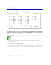
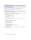

Example 1, Single Switch Operation
12-22 VLAN Operation and Network Applications
12.12.1 Solving the Problem
To set up this switch, users will be assigned to two new VLANs, red stations to the Red VLAN,
and blue stations to the Blue VLAN. The information below describes how the switch is
configured to create these two VLANs and how users are assigned to them.
1. The switch is set for 802.1Q operation.
2. VLAN ID 2 (Red VLAN) and VLAN ID 3 (Blue VLAN) are created using the Static VLAN
Configuration screen. The filter database FDB ID 2 and FDB ID 3 are automatically assigned to
the Red VLAN and Blue VLAN, respectively.
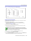
3. The Egress type for each port associated with a VLAN is set using the Static VLAN Egress
Configuration screen. In this example, the settings are as follows:
• For the Red VLAN
Ports 1, 2, and 3; Egress; UNTAGGED
• For the Blue VLAN
Ports 4, 5, and 6; Egress; UNTAGGED
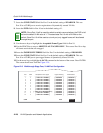
4. The ports 1 through 6 are configured as follows using the VLAN Port Configuration screen:
• Ports 1, 2, and 3 are set as follows:
PVID: 2
Acceptable Frame Types: ADMIT ALL FRAMES
Ingress Filtering: ENABLED
GVRP Status: DISABLED
• Ports 4, 5, and 6 are set as follows:
PVID: 3
Acceptable Frame Types: ADMIT ALL FRAMES
Ingress Filtering: ENABLED
GVRP Status: DISABLED
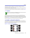
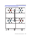
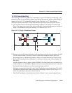
5. The VLANs and ports are now configured and enabled. Figure 12-11 shows the resulting VLAN
assignment to each port.