


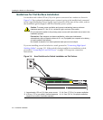
Installing the Switch on a Flat Surface
SecureStack B3 Installation Guide 3-7
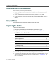
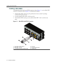
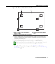
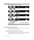
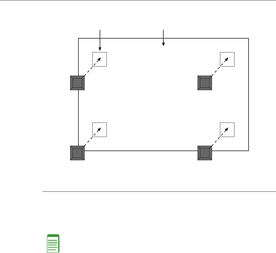
Figure 3-3 Chassis Bottom, Rubber Feet Placement
4. Removetheprotectivestripfromthe backofonerubberfootandpositionitona
markedlocationandpressfirmlyintoplace.Repeatthisproceduretoinstallthe
remainingthreerubberfeet.
5. Afterinstallingtherubberfeet,returntheswitchtoitsuprightposition.
6. Toinstallswitchesonaflat
surface,proceedto“GuidelinesforFlatSurface
Installation”onpage 3‐8.Forarackmountinstallation,proceedto“RackMounting
theSwitch”onpage 3‐9.
1 Bottom of chassis as seen when chassis is
resting on its back
3 Rubber feet with adhesive backing
(four)
2 Locations to install the rubber feet (four locations)
Note: If a number of switches are being installed in a stack, repeat steps 1 through 4 to
install the rubber feet on each switch before continuing with the installation.
À
Á
ÂÂ
ÂÂ