


Installing the Switch on a Flat Surface
3-8 Hardware Installation
Guidelines for Flat Surface Installation
Locatetheswitchwithin152cm(5ft)ofitspowersourceandonasurfaceasshownin
Figure 3‐4.Ifanoptionalredundantpowersystemisgoingtobeinstalledandconnected
tothe14‐pinRedundantPowerSupplyinputconnectorontherearoftheswitch,
referto
theinstallationguideshippedwiththeredundantpowersystem.
Ifyouareinstallingseveralswitchesinastack,proceedto“Connecting High‐Speed
StackingCables”onpage 3‐11.Iftheswitchisbeinginstalledasastandaloneswitch,
proceedto“ConnectingACandPoEPower”onpage 3‐
15forpowerconnection
instructions.
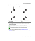
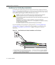
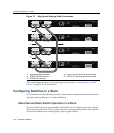
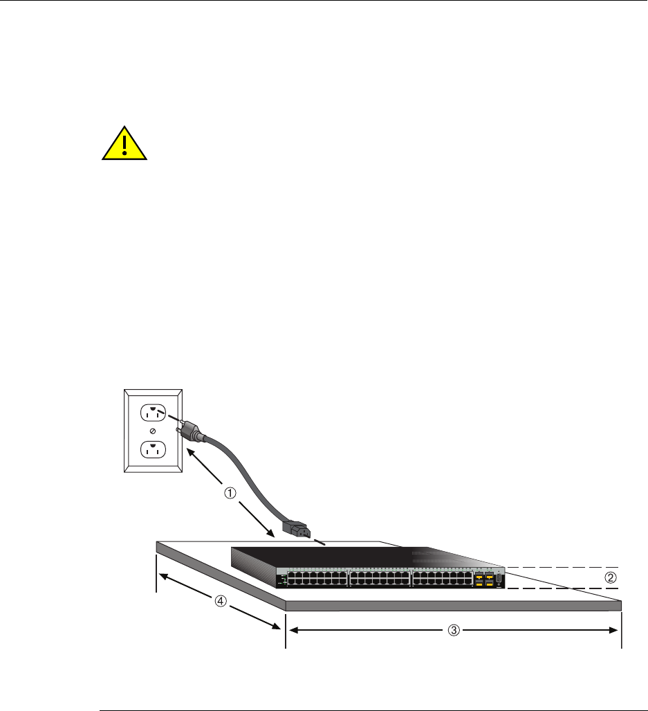
Figure 3-4 Area Guidelines for Switch Installation on Flat Surface
Caution: To ensure proper ventilation and prevent overheating, leave a minimum
clearance space of 5.1 cm (2.0 in.) at the left, right, and rear of the switch.
Do not connect the switch to the primary power source until instructed to do so later in the
installation process.
Precaución: Para asegurar una buena ventilación y evitar que el sistema se
sobrecaliente, deje un espacio mínimo de 5.1 cm (2 pulgadas) con respecto a los lados y
a la parte posterior del aparato.
No conecte el dipositivo a la fuente primaria hasta que no se le indique.
1 Approximately 152 cm (5 ft) from power source 3 44.5 cm (17.52 in.) for proper ventilation
2 4.45 cm (1.75 in.) per switch. (Vertical clearance
depends on number of switches stacked.)
4 41.9 cm (16.5 in.) for proper ventilation