


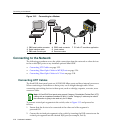
Connecting to the Network
SecureStack B3 Installation Guide 3-29
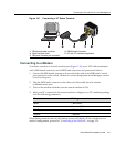
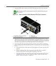
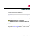
1. Removetheprotectivecovers(notshown)fromthefrontpanelLCfiber‐opticport
(port46inthisexample)andfromtheconnectorsoneachendofthecable.
2. InserttheLCcableconnectorintotheMini‐GBICLCconnectoruntilitclicksinto
place.
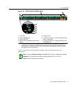
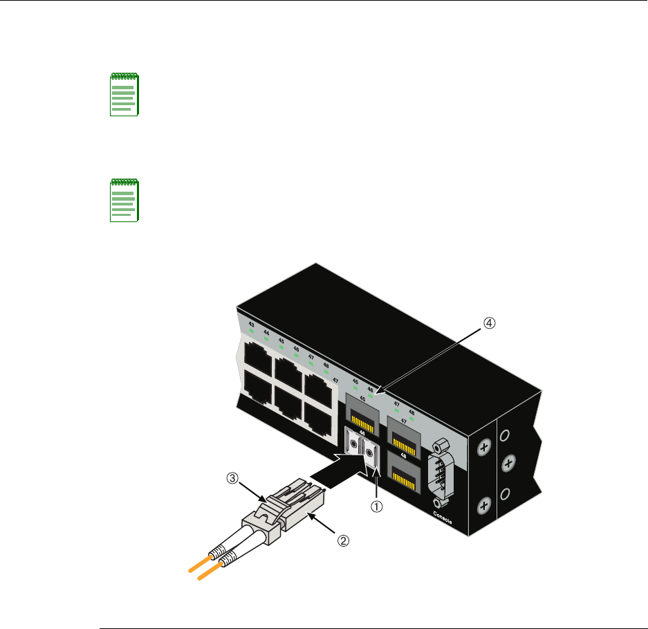
Figure 3-19 Cable Connection to LC Fiber-Optic Connectors
3. Plugtheotherendofthe
cableintotheappropriateportontheotherdevice.Some
cablesmaybeterminatedattheother endwithtwoseparateconnectors,oneforeach
fiber‐opticstrand.Inthiscase,ensurethatthetransmitfiber‐opticstrandisconnected
tothereceiveportandthereceivefiber‐opticstrandto
thetransmitport.
4. VerifythatalinkexistsbycheckingthattheportLink/ActivityLEDison(blinking
greenorsolidgreen).IftheLink/ActivityLEDisoff,performthefollowingstepsuntil
itison:
Note: Leave the protective covers in place when the connectors are not in use to prevent
contamination.
Note: To remove the LC cable connector, press on its release tab and pull it out of
Mini-GBIC LC connector.
1 Mini-GBIC MT-RJ port connector 3 Release tab
2 LC cable connector 4 Link/Activity LED