


NV3128 RS-422A Machine-Control Routing Switch 2-3
CHAPTER TWO - INSTALLATION
CAUTION: THE FOLLOWING INSTALLATION PROCEDURES ARE
INTENDED FOR QUALIFIED SERVICE PERSONNEL ONLY. TO
REDUCE THE RISK OF ELECTRIC SHOCK, DO NOT PERFORM
ANY SERVICING OTHER THAN THAT CONTAINED IN THE OPER-
ATING INSTRUCTIONS UNLESS YOU ARE QUALIFIED TO DO SO.
REFER ALL INSTALLATION AND SERVICE TO QUALIFIED PER-
SONNEL.
2.1 HARDWARE INSTALLATION
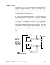
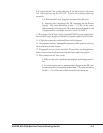
The following discussion makes frequent reference to Fig 2.1
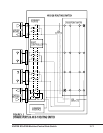
The NV3128 installs in a 19-inch EIA equipment rack. No fans or
cooling are required, but adequate free air space should be maintained
around the equipment.
1. Using the 2MM allen key supplied, remove the doors and vanity ear
covers from the front of the frames.
2. For installation in a telco style rack, reverse the front mounting
flanges on the frame prior to bolting the frame into the rack.
3. Lift the frame into the rack, and secure the frame to the rack by the
front mounting flanges using rack screws (not supplied).
4. Replace the doors on the front of each frame.
5. Operate the ejector/injector tabs on each of the active circuit
modules to disconnect them from the backplanes. Leave the modules
partially inserted in the card guides, but electrically disconnected.
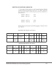
CAUTION: THE SETTING OF JUMPER J1 ON EACH POWER SUPPLY ASSEMBLY
MUST MATCH THE VALUE OF THE APPLIED AC INPUT VOLTAGE OR DAMAGE
TO THE EQUIPMENT MAY RESULT.
6. Unscrew its captive latch and remove the PS2001-01 Power Supply
Assembly from the frame by pulling straight back on its cover/handle.
Determine the value of the AC line voltage supplying the rack. Ensure
that the setting of Jumper J1 on the supply matches the value of the
applied line voltage. Repeat for the redundant supply, if present.
7. Re-insert power supply(ies) in the frame. Ensure its connectors
mate with the backplane before seating the power supply assembly into
the frame.