


NV3128 RS-422A Machine-Control Routing Switch 2-4
8. Connect the AC line cord at the rear of the frame and to the input
AC, which powers up the NV3128. Ensure the system powers up
correctly.
a. LEDs on the Power Supply front panel should glow.
b. Measure the voltages at the DC tespoints on the Power
Supply. The value should be within +/- 1VDC of the value
silkscreened at the test point. (If no boards are plugged in, the
voltages will be very high, around ±9 and ±20 volts.)
9. Disconnect the AC line cord(s) from the PS2001 power supply(ies).
Secure the Power Supplies with the front panel captive latch screws.
10. Cable the system as explained later in this chapter.
11. Set jumpers on the Command Interpreter (older systems only) as
discussed later in this chapter.
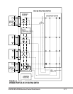
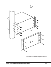
12. Engage all active circuit modules. Ensure they are plugged into
their correct slots as silkscreened on the frame and front panels.
13. Re-connect the AC line cords.
a. LEDs on the active modules should glow, indicating power is
on.
b. As an extra precaution, measure the voltages at the DC test
points on each active module in the frame. The value should be
within +/-5% of the value silkscreened at the test point.