


NV3128 RS-422A Machine-Control Data Routing Switch 4-5
4.2 CIRCUIT OPERATION
The following discussion provides an overview of circuit operation for
each of the circuit boards in the NV3128 Router frame. Because repair
is done by replacing modules rather than repairing them, schematics
and bills of material are not provided but may be requested from
NVISION Technical Support.
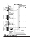
4.2.1 I/O CONNECTOR INTERFACE
ASSY: EM0038-XX
RS-422A Machine Control data enters the NV3128 through PC-
mounted D connectors on this passive connector interface assembly.
On each D connector, an RC circuit AC couples the input shield
terminal to ground. High density Metral connectors route the signals
back to the active I/O and Command Interpreter Modules.
A bayonet style BNC connector receives the reference video input and
loops it through to a second to facilitate daisy chain connections.
Alarms and changeover connections arrive via Phoenix terminal blocks.
Two spare BNCs are provided to accomodate possible future
customization.
D connector sets carry command information from the external router
control system, the diagnostic interface, and (on older frames) the
parallel interface. The RS-232 and RS-422 interfaces are 9-pin D
connectors, and the parallel interface is a 37-pin D. The primary
control and parallel connectors have neighboring connectors that can
be used for loop through. Note that the primary ports and their loop-
thru connectors are not equivalent; you must connect the control
system directly to the primary port.
4.2.2 SIGNAL BACKPLANE:
ASSY: 0039-XX
This captive, passive assembly mounts the high-density Metral
connectors that carry the intra-frame signal traffic.