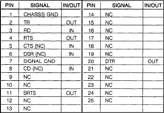
SERIAL INTERFACE
Input Connector
Cable side connector 25 pin (male)
Printer side connector 25 pin D-SUB type (female)
Note 2)
Note 2)
Note 1)
Note 1)
Note 1: As shipped from the factory CTS, DSR, and DC are NC (NO CONNECTION).
If DSR or CD is to be used, perform the following to the jumpers J1, J2, J4 and J5
on the circuit board in the printer.
• If DSR is to be used, cut J2 and connect a jumper at J5.
• If CD is to be used, cut J1 and connect a jumper at J4.
Note 2: RTS and CTS are connected within the printer.
If CTS is to be used, cut J3 and connect a jumper at J6.
CAUTION: Changes in jumper connections should only be made by an authorized
Epson Service representative.
22


