


Input/Output Signal Descriptions
1. Printer Input Signals
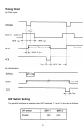
* RD (RECEIVED DATA)
This line is the data reception line for the serial signals from the computer. The data
consists of a start bit, data (parity bit), and stop bit.
Data length 7/8 bits.
With/without parity bit.
Selectable by DIP switches
Odd/even parity
* CTS (CLEAR TO SEND)
A data transmission control signal, NC (No Connection).
OFF: Data transmission may not be performed.
ON: Data transmission is possible.
* DSR (DATA SET READY)
A signal that displays the state of the modem, NC.
OFF: The modem cannot receive/transmit data.
ON: The modem can receive/transmit data.
CD (CARRIER DETECT)
A signal that indicates whether or not the carrier is detected, NC
OFF: No Carrier
ON: Carrier
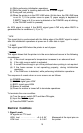
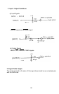
2. Output Signals from the Printer
*TR (TRANSMIT DATA)
Employed for the X-ON/X-OFF and ETX/ACK control.
* RTS (REQUEST TO SEND)
On (SPACE) state is continuously output.
*SRTS
This is a handshaking signal representing the printer’s BUSY state.
OFF: BUSY
ON: READY
* DTR (DATA TERMINAL READY)
This signal controls the state of the modem.
OFF: Modem transmitting/receiving cannot be performed.
ON: Modem transmitting/receiving can be performed.
23