


A794 Owner’s Guide Chapter 5: Communication Interface
March 1999 37
RS-232C Technical Specifications
This section describes the pin settings for the connectors and the RS-232C interface
parameters. The RS-232C parameters are selected through the configuration menu
feature. The RS-232C parameters must match those of the host computer.
For more information about See these sections or
documents
Configuration menu feature A794 Owner’s Guide
RS-232C settings “RS-232C Serial Interface Settings”
in the A794 Service Guide
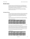
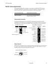
Communication Connectors
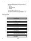
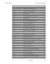
The following illustration shows the RS-232C communication connectors and pin
assignments. The connectors are located at the rear of the printer, and are specified as
male, DB9, 9-pin D-shell, and female DB25, 25-pin with RTS and CTS pins connected.
9-pin DB-9 Connector 25-pin DB-25 Connector
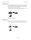
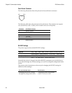
Power Connector
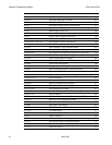
With RS-232C, the printer is always remotely powered. The following illustration shows
the power cable connector and pin assignments. The power cable connector is a 3-pin
mini DIN plug and is located at the rear of the printer.
3 Not Used
1 +24 Volts
Function Pin Numbers Function
Ground 2
Shell - Shield
Not Used
Not Used
Not Used
Not Used
Not Used
9
10
11
12
13
14
15
1
2
3
4
5
6
7
8
Frame Ground & Shield
Transmit Data
16
17
18
19
20
21
22
23
24
25
Receive Data
RTS
CTS
DSR
Logic Ground
Not Used
Not Used
Not Used
Not Used
Not Used
Not Used
Not Used
DTR
Not Used
Not Used
Not Used
Not Used
Not Used
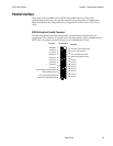
Function
Function
Pin Numbers
DSR 6
RTS 7
CTS 8
Not Used 9
1 Not Used
2 RXD
3 TXD
4 DTR
5 Logic Ground
Shell-Frame Ground