


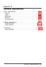
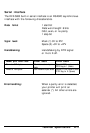
Interface Specifications
The DFX-5000 is equipped with both a parallel and a serial
interface.
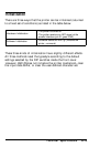
WARNING: Do not plug in the built-in parallel interface
cable and an optional interface cable at the same time
because this may damage your printer.
However,
simultaneous attachment of the built-in serial interface
cable is possible with either built-in parallel or any
optional interface cable, but not both.
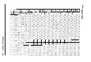
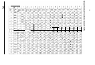
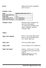
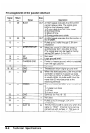
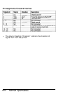
Parallel interface
Connector pin assignments and a description of their respective
interface signals are shown in the table on the following pages.
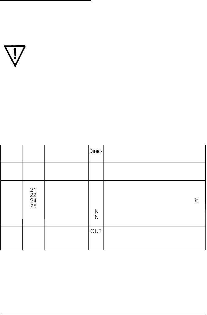
Signal
Return
Direc-
Pin
Pin
Signal
tion
Description
1
19 STROBE
IN
STROBE pulse to read data in. Pulse
width must be more than 0.5
microseconds at the receiving terminal
2
20
DATA
1
IN
These signals represent information of
3
::
DATA 2
IN
the 1st to 8th bits of parallel data,
4
DATA 3 IN
respectively, Each signal
IS
at HIGH level
5
23 DATA
4
IN
when data is logical 1 and LOW when
II
IS
6
DATA
5
IN
logical 0.
7
2
DATA
6
8
26
DATA
7
I:
9
27
DATA 8
IN
10
28
ACKNLG
OUT
About a 12-microsecond pulse. LOW
indicates that data has been received
and that the printer IS ready to accept
more data.
Technical Specifications B-7