


(c) Set the adequate ASCII code data to be printed. To obtain low logic
level signals, connect the data transfer line required for printing (pin
Nos. 2 to 9) to GND level (pin No. 33, etc.)
l Example of printing’?”
“Z”=[5.
A]~=(0101
1010)
In this case, connect pin Nos. 2, 4, 7 and 9 to pin No. 33.
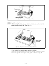
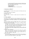
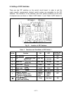
5. Construction of MX-80 F/T
The EPSON MX-80 F/T Dot Matrix Printer consists of the following three major
functional blocks.
(1) The model 3310 printer mechanism
(2) Control circuit board
(3) Power circuit
These three blocks are housed in a plastic case and are connected to one
another.
5.1. Printer mechanism
The model 3310 printer mechanism has been developed by Shinshu Seiki with
the technology in the precision and electronic industry fields amassed through
its long association with SEIKO, manufacturer of the world-famous SEIKO
watches.
The printer mechanism contains two stepper motors. One is to move the print
head to the next print column position, and the other is to advance the paper.
(1) Stepper motor for head carriage
The stepper motor for head carriage is controlled under LSI “8041” called
“slave CPU”. The CPU knows the current printing position at any given
time, and the print head is stopped at the last printing position. Then, the
CPU seeks the shortest travel way to the next print line.
This feature and bi-directional printing enable the Printer to perform the
logical seeking function which minimizes the head travel time to the next
print line.
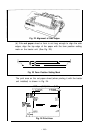
(2) Stepper motor for paper feed
Paper is fed by the stepper motor, like the head carriage. One complete
rotation of the stepper motor corresponds to 1/3 inch paper advance. In
the MX-80 F/T, the operator can select any paper feed length under soft-
ware control (described in detail later).
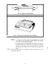
(3) Micro print head
The micro print head has 9 dot wires to form 9 X 9 dot matrix characters. 9
wires form more legible characters than those formed by 7 wires. The print
head for the 3310 printer mechanism is quite compact.
-23-