


LIST OF FIGURES
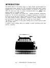
Fig. 1
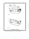
EPSON MX-80 F/T Dot Matrix Printer
..............................
1
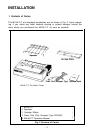
Fig. 2
Contents of Carton.
..............................................
2
Fig. 3
Removal of Shipping Screws
.....................................
.4
Fig. 4
Removal of Printer Lid.
...........................................
5
Fig. 5
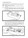
Cartridge Ribbon Setting.
.........................................
6
Fig. 6
Cartridge Ribbon Setting.
.........................................
6
Fig. 7
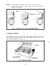
Examples of Correct and Incorrect Ribbon Setting.
...................
7
Fig. 8
Separator Installation
.....................
7
........................
Fig. 9
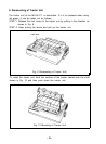
Dismounting of Tractor Unit,
.....................................
.8
Fig. 10 Mounting of Tractor Unit
...............................................................................
.8
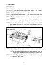
Fig. 11 lnsertion of Fanfold Paper.
.
9
Fig. 12 Raising of Sprocket Lock Levers
..................................
10
Fig. 13 Engagement of Paper Feed Holes on Feeding Pins.
..................
10
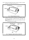
Fig. 14 Printer with Fanfold Paper Set Completely
.........................
11
Fig. 15 Example of Paper Arrangement.
..................................
11
Fig. 16 Top of Form Position Setting.
....................................
12
Fig. 17 Loading of Roll Paper (1)
........................................
13
Fig. 18 Loading of Roll Paper (2)
........................................
14
Fig. 19 Loading of Roll Paper (3)
........................................
14
Fig. 20 Loading of Cut Paper Sheet.
.....................................
15
Fig. 21 Adjustment of Inserted Paper Position
.............................
15
Fig. 22 Alignment of Side edges.
........................................
16
Fig. 23 Form Position Setting Mark
......................................
16
Fig. 24 Print Area.
.....................................................
16
Fig. 25 Setting of Cut Paper Sheet.
......................................
17
Fig. 26 Printer with Cut Paper Sheet Set Completely
.......................
17
Fig. 27 Gap Adjustment.
...............................................
19
Fig. 28 Switches and Indicators on Control Panel
..........................
20
Fig. 29 Control Circuit Diagram.
.........................................
24
Fig. 30 Driver Circuit Diagram
...........................................
25
Fig. 31 Location of DIP Switches
........................................
27
Fig. 32 Parallel Interface Timing
.........................................
31
Fig. 33 Replacement of Print Head.
.....................................
.45
-(3)-