SED1520 Series
EPSON 2–11
SED1520
Series
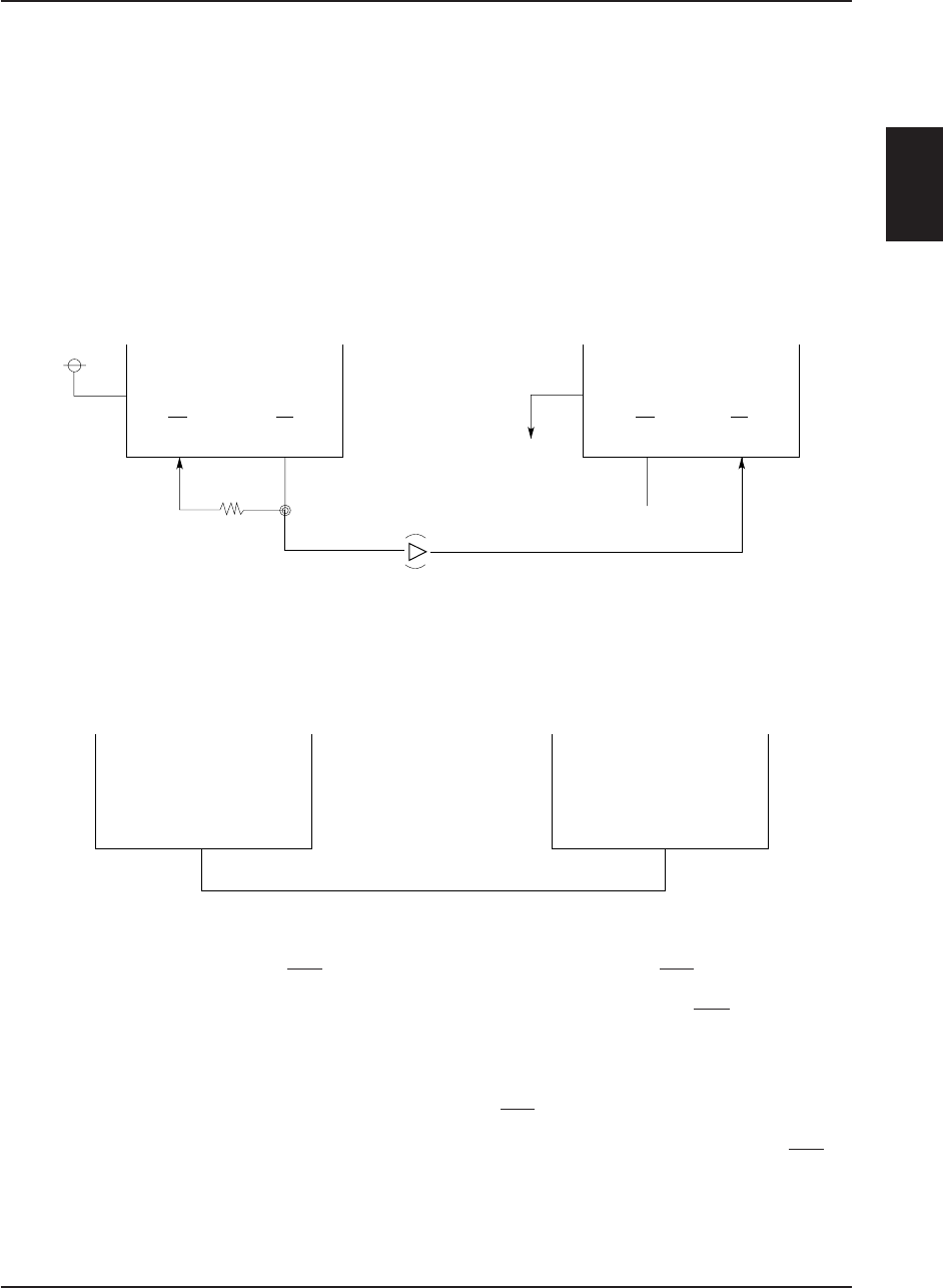
*1 If the parasitic capacitance of this section increases, the oscillation frequency may shift to the lower
frequency. Therefore, the Rf oscillation frequency must be reduced below the specified level.
*2 A CMOS buffer is required if the oscillation circuit is connected to two or more slave MPU chips.
Oscillator Circuit (SED1520
*
0A Only)
A low power-consumption CR oscillator for adjusting
the oscillation frequency using Rf oscillation resistor
only. This circuit generates a display timing signal.
Some of SED1520 and SED1522 series models have a
built-in oscillator and others use an external clock. This
difference must be checked before use.
Connect the Rf oscillation resistor as follows. To sup-
press the built-in oscillator circuit and drive the MPU
using an external clock, enter the clock having the same
phase as the OSC2 of mater chip into OSC2 of the slave
chip.
• MPU having a built-in oscillator
• MPU driven with an external clock
Reset Circuit
Detects a rising or falling edge of an RES input and
initializes the MPU during power-on.
• Initialization status
1. Display is off.
2. Display start line register is set to line 1.
3. Static drive is turned off.
4. Column address counter is set to address 0.
5. Page address register is set to page 3.
6. 1/32 duty (SED1520) or 1/16 duty (SED1522) is
selected.
7. Forward ADC is selected (ADC command D0 is
1 and ADC status flag is 1).
8. Read-modify-write is turned off.
The input signal level at RES pin is sensed, and an
MPU interface mode is selected as shown on Table 1.
For the 80-series MPU, the RES input is passed
through the inverter and the active high reset signal
must be entered. For the 68-series MPU, the active
low reset signal must be entered.
As shown for the MPU interface (reference example),
the RES pin must be connected to the Reset pin and
reset at the same time as the MPU initialization.
If the MPU is not initialized by the use of RES pin
during power-on, an unrecoverable MPU failure may
occur.
When the Reset command is issued, initialization
Master chip Slave chip
M/S M/S
OSC1 OSC2 OSC1 OSC2
V
SS
*2
*1
Rf
Open
V
DD
(CS) (CL) (CS) (CL)
Y driver
CL2
SED1521F
AA
CL


