TM200 Service Manual
- 8 -
Note:
The ha
ndshak
i
n
g, da
t
a
word length,
b
a
u
d
rate, a
n
d p
a
ri
ty
depend
on th
e
DI
P swit
c
h
settings.
Data transmi
tted
from th
e
p
r
i
n
ter h
a
s 1
st
o
p
b
i
t (fi
x
ed
)
Sw
itch
i
ng be
tw
ee
n
on
lin
e a
nd
offl
ine
T
he pr
int
e
r d
o
es no
t ha
v
e
a
n
onl
i
ne/o
ff
l
in
e swit
ch. The
pr
in
t
e
r
g
o
e
s
o
ff
lin
e
:
When t
he cov
e
r i
s
op
en
When an
erro
r ha
s occur
r
ed
When the pr
int
e
r st
ops
pri
n
ti
ng
d
u
e
to a pa
per-en
d
(i
n cases
when
an
emp
ty
pa
per
sup
p
l
y
i
s
d
e
tec
t
ed
by
ei
ther
pa
per
rol
l
end
d
e
t
ecto
r
or
th
e pap
e
r
rol
l
ne
ar- end
d
e
tect
or
wit
h
a p
r
i
n
ti
ng ha
lt
feat
ure u
s
ing
ESC c
4)
Inte
rfa
ce
co
nn
e
c
t
o
r te
rmina
l
a
ssign
m
e
nt
s a
n
d sig
n
a
l
fun
c
tio
ns a
r
e
d
e
scrib
e
d
in th
e
t
a
b
l
e
be
lo
w
.
T
M200
serial printer s
t
atus and signal
s
:
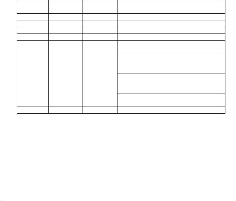
Pin number Signal name Signal
direction
Function
1 FG --- Frame ground
2 TXD Output Transmit data
3 RXD Input Receive data
4 RTS Output Same as DTR signal (Pin 20)
This signal indicates whether the host computer
can receive data.
SPACE indicates that the host computer can
receive data, and MARK indicates that the host
computer cannot receive data.
When DTR/DSR control is selected, the printer
transmits data after confirming this signal (except
when transmitting data by DLE EOT, and GS a).
6 DSR Input
When XON/XOFF control is selected, the printer
does not check this signal.
7 SG --- Signal ground


