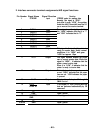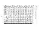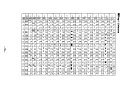
2. Interface connector terminal assignments and signal functions
Pin Number
1
Signal Name
STROBE
2 DATA 1
3
DATA 2
4
DATA 3
5
DATA 4
6 DATA 5
7
DATA 6
8
DATA 7
9
DATA 8
10
ACKNLG
11
BUSY
12
PE
13
SLCT
14
AUTO
FEED XT
15
16
17
18
19 or 30
NC
GND
CHASSlS
GND
NC
GND
Signal Direction
Function
lnput
STROBE pulse for reading data.
Normally, this signal is “HIGH”.
just after it goes “LOW”, the printer
reads the data. Pulse width must be 0.5
µs or more at the receive terminal.
Input
These signals are ths eight parallel data
Input
tits. “HIGH” indicates that the tit is "1"
and "LOW" indicates that is "0".
Input
Input
Input
Input
Input
Input
Output
This signal indicates that theprinter is
ready to receive data. Under normal
conditions, it is “HIGH” and goes
“LOW for approx. 10µs.
Output
This signal indicates whether the printer
can or cannot receive data. When this
signal is “HIGH”,
it indicates that the
printer cannot receive data.
When it is “LOW”, it indicates that the
printer Is ready to receive data.
Output
This indicates whether paper is present
or not. “HIGH” indicates that the paper
has run out. “LOW indicates the paper
is present.
Output
This signal is pulled up to +5V through 3.
3ΚΩ 3ΚΩ resistor.
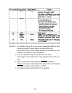
Input
If this signal is “LOW. printing and line
feed are performed automatically by CR
command.
Signal ground
chassis ground
Signal ground
-68-


