Section 3: Instrument
15
3.3.2.5 Interfacing to the RS-232 option
The optional RS-232C interface is provided on the P1 connector. The configuration is 9600 baud,
Even Parity, 8 Bits, 1 Stop, all received characters are echoed. The ground of the RS-232C inter-
face is connected to the frame (AC power) ground however it is isolated from the sensor ground,
see section 3.1.1.
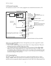
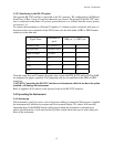
To connect the instrument to a Personal Computer a 3 conductor cable is required; with wires to
be placed in the screw terminals of the XDT at one end, and with either a DB9 or DB25 female
connector at the other end:
Note that some Personal Computer Programs may require that RTS & CTS and/or DTR & DSR
are jumpered for proper operation. This jumpering may be accomplished at the DB9 or DB25
connector.
CAUTION: Connecting the RS-232C interface on instruments which do not have the option
installed, will damage the instrument.
Refer to appendix K for details on the protocol used on the RS-232C interface.
3.4 Operating the Instrument
3.4.1 Starting up
The instrument is ready for use as soon as the power cabling is connected. When power is applied
the instrument will initialize its program and for a moment display XEN, then it will enter the
Operating State. If the MODE button is held pressed while the instrument is performing its
power-up initialization, it will enter the Set-Up State, which allows the user to select setup vari-
ables of the instrument.
Signal Name
instrument P1
pin #
DB9 pin or DB25 pin
Transmit Data 9 TXD or Tx 2 3
Receive Data 10 RXD or Rx 3 2
Signal Ground 11 GND 5 7
RTS n.c. 7 4
CTS n.c. 8 5
DTR n.c. 4 20
DSR n.c. 6 6


