XDT User’s Manual Appendices
55
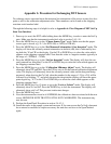
Appendix L: Procedure for Exchanging XDT Sensors
To exchange sensors one must know the measured low attenuation of the sensor at some low dew-
point as well as the calibration adjustment value. These numbers can be found on the shipping
container serial number label.
Through the following steps it is helpful to refer to Appendix A: Flow Diagram of XDT Set-Up
State User Interface
1. Power up (or reset) the XDT while holding down the MODE key, in order to enter the Set-Up
state. Make sure that the instrument in unlocked, refer to section 3.4.5.-10.
2. Press the MODE key to go to the “Choose Sensor Type” mode. Make sure that the proper
sensor type is chosen, e.g. XT1 (for XTR-100) or XT6 (for XTR-65).
3. Press the MODE key to go to the “Set Measured Attenuation @ low dewpoint” mode. The
display will show the currently entered attenuation in decibels (dB), this is indicated by hav-
ing both the °C and °F on the display. Use the UP or DOWN keys to select the value which
appears on the shipping container label. Note that this value is a negative number typically in
the range of -18.0DB to -14.0DB.
4. Press the MODE key to go to the “Set low dewpoint” mode. The display will show the cur-
rently entered low dewpoint. Use the UP or DOWN keys to select the value which appears on
the shipping container label.
5. Press the MODE key to go to the “Calibration Midrange Adjust” mode. The display will
alternately show CAL and ADJ. Press the UP key once to see the entered calibration adjustment
value. The display will alternately show the currently entered value and the dewpoint being
measured, when showing the Cal Adj value the number (in the range of -2.0 to +2.0) will be
followed by a blinking “X”, and when showing the dewpoint the display will have the appro-
priate legend e.g. °C. Use the UP or DOWN keys to select the value which appears on the
shipping container label.
6. Press the MODE key five (5) times to go to the “Lock or Unlock” mode. The display will
alternately show UN and LOC. Press the DOWN key to lock the instrument. The display will
alternately show only LOC.This prevents inadvertent changes.
7. Press the MODE key once.
8. Now the instrument has stored in it’s EEPROM, the calibration values associated with the new
sensor, HOWEVER NOTE THAT IT IS STILL NOT CALIBRATED. The instrument may
now be reset.
9. Perform the SpanCheck Procedure in section 3.4.4.3.1.
10. Install the sensor in the sample system and measure. If for some reason the Cal Adj value must
be re-entered or modified to improve accuracy the unit does not have to be SpanChecked
again.


