XDT User’s Manual Appendices
46
Appendix G: Dewpoint Response time Analysis
Manufacturers of dewpoint sensors will make unbelievable claims of speed. But without support-
ing data revealing the conditions under which the measurements were made, such as flow rate,
temperature, the dewpoint at which the test was performed, and most importantly the units of
measure. This last aspect can be extremely deceiving, consider the following example.
At Xentaur we have performed a variety of tests to determine the response time of ours as well as
the competitor’s sensors. For this discussion let’s consider a step change of -40°C to -60°C dew-
point, in other words a challenging but typical dry-down. An XTR-100 sensor w/SS sintered filter
was placed in an electro-polished stainless steel manifold, the temperature was 23°C and the sam-
ple flow rate was 3 LPM. The dewpoint was generated with a computer controlled mass flow
valve gas dilution dewpoint generator, and was verified with a NIST and NPL calibrated MBW
chilled mirror. The system was allowed to achieve equilibrium at -40°C dp overnight, then the
dewpoint was abruptly changed to -60°C, the change is depicted below as time 0.
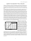
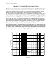
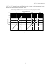
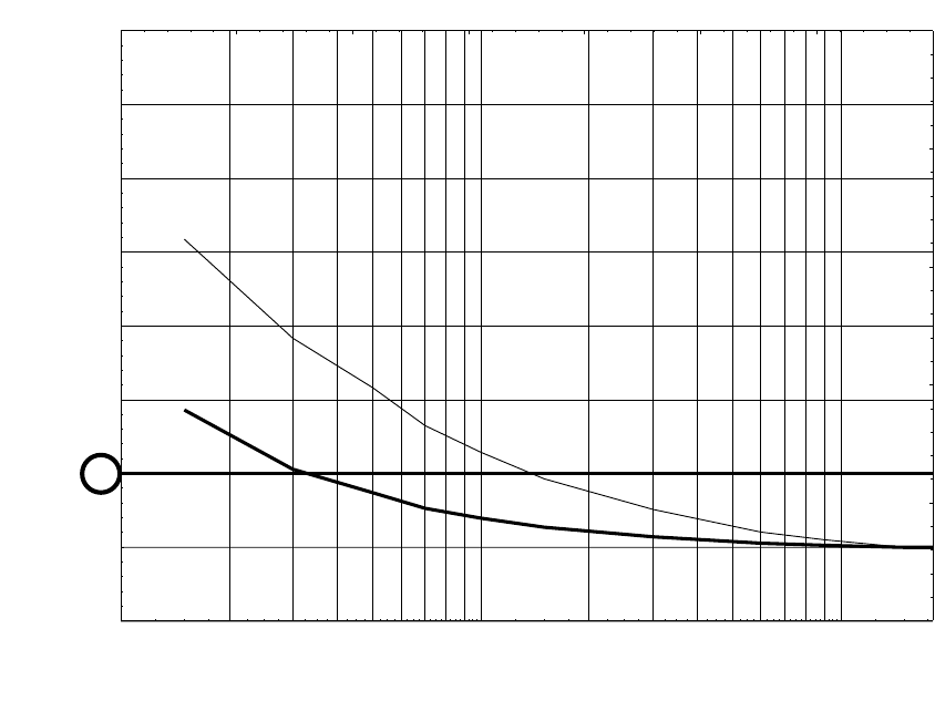
The graph below shows the percent change of recorded dewpoint (°C), the same data is also
shown in percent change of the recorded dewpoint converted to ppmV. It is immediately obvious
how a sensor that has response times exceeding ten minutes can be claimed to have response time
of 3 minutes, simply by manipulating the units of measure. The logarithmic relationship between
dewpoint and ppmV makes the ppmV reading appear faster. Since the response time is stated in
percent change, the units of measure are automatically hidden from the audience.
30
40
-50
˚C = 50%
60
70
80
90
-60
˚C = 100%
110
1
2
3
4
5
6
7
8
9
10
20
30
40
50
60
70
80
90
100
%
c
h
a
n
g
e
o
f
p
p
m
V
c
o
n
v
e
r
t
e
d
m
e
a
s
u
r
e
m
e
n
t
%
c
h
a
n
g
e
o
f
˚
C
m
e
a
s
u
r
e
m
e
n
t
Time (minutes)
Percent Change


