


For detailed instructions on how to connect the drives to the optional
floppy disk controller card, consult the documentation supplied with the
card itself. The drive cables for drives A and B are normally connected to
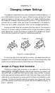
connector CN5 on the system board (shown in Figure A-2). If a different
cable was supplied to connect the drives to the optional controller card,
make a careful note of how the original drive cable was connected, and
remove it from the computer. Keep it in a safe place, in case you need to
remove the optional controller for any reason.
FRONT
J2
/
6M and 6N
/
7M and 7N
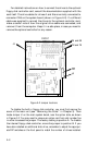
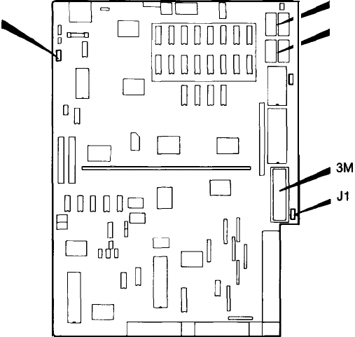
Figure A-2. Jumper locutions
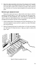
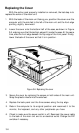
To disable the built-in floppy disk controller, you must first remove the
cover of the main unit (see “Removing the Cover” in Chapter 3). Then
locate Jumper J1 on the main system board, near the option slots, as shown
in Figure A-2. You may need to remove an option card from slot number five
in order to access this jumper. The factory setting is position A. To disable
the internal floppy disk controller, move the jumper to position B. If you
have also installed an additional disk drive, remember to adjust the appropri-
ate DIP switches on the front panel to match the number of drives installed.
A-2